You may well ask: What are the alternatives?
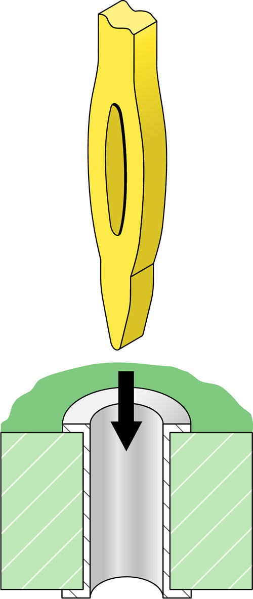
First, I should explain that a compliant pin is one that when inserted into a plated-through hole, creates a spring force against the barrel of the hole that creates a gas-tight joint that is just as good electrically as a solder joint. It has the additional advantage of not exposing the printed circuit board to a heat cycle, especially important on high layer count backplanes.
Compliant pin technology first started to appear in the 1970s. This technology was developed by and for the telecom industry, notably ATT, or Western Electric at the time.
Prior to compliant pins, the choices were solder and rigid square pins with no compliant section. Both were problematic. Wave soldering was not possible for pins with long tails. Vapor phase reflow was possible, but exposed the board to very high temperatures. The rigid square pins required a very tight diametric tolerance (±002) that is difficult to hold and increased board cost.
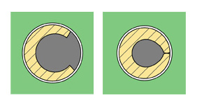
One of the first compliant pins that came from Western Electric was the C-pin. It has a coined C shaped portion that when pushed into the hole, compressed in a very controlled way, creating a gas-tight joint around about 70% of the plated hole surface area. This kind of compliant pin could withstand even the rigors of wire wrapping, not uncommon at that time, where a machine would wrap a small wire around the square part of the pin, also creating a gas-tight joint with the wire. This put a lot of torsional force on the pins and the compliant joint. With 0.025 in. square into 0.040 in. plated through holes, and pins on a 0.100 or 0.125 in. pitch, this was a practical solution for making backplanes.
Compliant press fit pins had other advantages as well:
- They are repairable. One can extract or punch out a pin easily and replace it with a new pin.
- The pin can extend well beyond the rear surface of the backplane, to allow mating to connectors on both ends. For example, you can pass circuits through a backplane to mate with a cable connector
- Compliant pins can be wire wrapped, making it very quick to produce a prototype backplane for a low speed less than 622 Mbps. It is also a low cost way to make a small batch of backplanes rather than pay for the design and tooling needed for multilayer boards.
In the beginning, there was a lot of skepticism that such a pin termination would survive environmental conditions in the field, so a lot of testing was done to assure that these pins would work well in the field 40 years in the future in Alaska or Panama. Customers were worried about many failure modes from corrosion to creepage of the board over time and temperature extremes. Out of this effort came Bellcore (Now Telcordia) specifications for testing. The best way to evaluate the integrity of the compliant pin-to-board connection in production is by pulling a pin and measuring the force required to pull it out. In the beginning, it was common to specify retention of 30 N (6.7 lb) per pin. Today, with the smaller pins that never see wire wrap torque or other forces that will break the joint, it is common to specify retention forces as low as 2.5 N, about half a pound. This is possible because the pins are tightly locked into the connector and not subject to the abuse that the pins were in the early days. Telcordia GR 1217 Core specification requires that compliant pins can be removed and replaced at least twice without compromising retention force or deforming the holes.
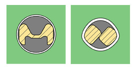
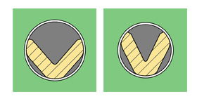
Each connector manufacturer tried to differentiate their compliant design to avoid paying royalties on existing patents. A variety of shapes emerged: Eye of the needle, Action pin, Sigma, S pin, and a few more all were developed to serve the market.
The advantages of compliant pins quickly won over the skeptics and by the early 80s, nearly all backplane connectors used press fit tails.
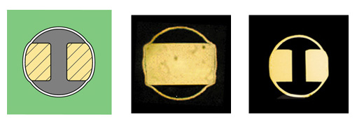
Over the years, plated through hole diameters have dropped dramatically from 0.040 in. down to 0.032 in., on down to 0.022 in., then 0.018 in. and now as low as 0.016 in. and even 0.012 in. as a result of higher pin density and the signal integrity advantages of small holes. Today, the vast majority of connector manufacturers have adopted the eye of the needle, especially after the patent ran out for this pin. The major advantage of the eye of the needle is that it is able to scale down as the size of the pin and the size of the hole has decreased. In addition the eye of the needle is relatively easy to stamp, especially compared to more complex designs.
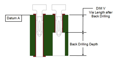
Image courtesy of FCI Electronics.
Press fit has signal integrity advantages as well. It is now practical to back drill the plated through hole up to a level just below the compliant “football” of the pin. This eliminates electrical stubs caused by the barrel of the platted through hole below the pin itself. The smaller the diameter of the plated through hole, the better signal integrity that can be achieved. Thus compliant pin technology has enabled connectors and backplane channels to run above 25 Gbps with the potential to go greater than 56 Gbps.
Much of the credit for improved compliant pin performance has to go to the PCB fabrication houses who have consistently improved the quality of drilling, plating, and surface consistency. Good PCB fabricators are able to achieve aspect ratios (diameter of the hole / thickness of the board) of up to 15:1 in high volume production today.
Think about the evolution in this basic technology we have seen since its emergence just a few decades ago. Pretty amazing!
Leave a Reply
You must be logged in to post a comment.