By Marty Houlroyd
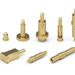
 Spring-loaded pins are rapidly finding new applications in modular product design. Also referred to as SLCs (spring-loaded connectors), this product resolves many of the manufacturing issues like misalignment, coplanarity, and tolerance stack up that can plague traditional pins and sockets. However, as flexible as SLCs are you need to be aware of potential issues lurking around the corner. Here is a list and explanation of 10 items to consider:
1. Starting Height: Be aware that when you look at some manufacturer’s catalog or website, the starting height of the spring pin is NOT where you want to make your critical
signal connection. The starting SLC height will exhibit a light pre-load force and its contact resitance will be very high. Typically, the true engagement height between your modules should be somewhere near the mid-stroke of the spring pin.
2. Termination: If you are considering using an SLC with a solder tail, make sure the length of the tail will protrude at least a minimum of .020″ below your PCB in order to ensure you produce a good solder fillet. If the tail is too short and does not protrude beneath the PCB, you will have cold solder joints.
3. Stroke: The amount of SLC stroke you require is a function of your module stacking tolerance. Make sure that you have calculated not only the desired target mating height, but have also taken into account the maximum distance between modules due to assembly tolerance. Ideally the SLC stroke will be long enough to cover the worst case separation distance between your PCBs.
4. Plating The amount of gold plating you require on the piston and shell should be determined by two factors: 1) How many cycles do you anticipate needing in your application. 2) Is the operating environment corrosive in any way?
5. Current Rating: Can the SLC design handle your current requirements? It is a really bad idea to use multiple spring pins as a current divider. If one SLC fails, the resistance and heat goes up on the remaining SLCs and they burn out. Use an SLC rated for your requirements.
6. Packaging: For ease of assembly, improved part placement on your PCB, if you require several SLCs in an array form, have your supplier package them into a thermoplastic insulator. Another route is to use SLCs that can be packaged on tape and reel for high-speed placement. Never find yourself placing several SLCs onto
a PCB by hand.
7. Assembly Method: When selecting SLCs consider how you intend to assemble them in mass-production onto your PCBs. As highlighted in item 6,, make sure the parts you select can either be supplied on tape and reel, or can be packaged in thermoplastic insulators. Make sure the part you select can be assembled using automation.
8. Signal Integrity: Be aware, especially with hollow piston SLCs, that if your application is dynamic and subjected to shock and vibration, the piston may become concentric to the shell, leaving the signal to attempt to pass through the spring. If the spring is non-conductive, this may cause a momentary open circuit (for a few millionths of a second) Is that enough time to make your logic reset or turn off? Be aware of this possibility in DYNAMIC applications’.
9. Force: Calculate the accumulative force when using multiple SLCs. For example, if you holding your module together with a magnetic latch, can the magnets overcome the total force produce by multiple SLCs? Also, do not operate SLCs at their initial preload height, the force is very light and the contact resistance will be high.
10. Mating side: If not cost prohibitive, you can simply mate the piston of the SLCs to gold plated pads on the opposing circuit board. If gold plated lands cannot be provided, then there are mating components called “Target Connectors” which are accessory assemblies providing gold plated brass pins to mate to.
Martin Houlroyd is the owner of ConnectorTechologies.com. He has worked in the interconnect industry for over 40 years.

Leave a Reply
You must be logged in to post a comment.