By Ed Cady, Contributing Editor
QSFP or Quad Small Form-factor Pluggable connectors and cables are long time primary type of high-speed IO interface interconnects. This four-lane system is broadly used to connect server, storage, switch, video and communication systems. Major market segment implementations include cloud datacenters, enterprise datacenters, HPC (high performance computing) labs, camera surveillance systems, Internet provider systems and machine vision systems.
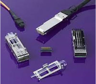
This first generation QSFP interconnect system gradually supplanted the older CX4 SFF- 8470, another four-lane interconnect, both used for 10 G Ethernet IEEE802.3ak, InfiniBand SDR 4×2.5 G and DDR 4×5 G as well FibreChannel ISL 4×8 G. CX4 is a two-piece copper contacted connector system while the QSFP receptacle connector has stamped copper contacts but the cable plug is a PCB with plated pads. Mated QSFP connectors have typically cost less than the CX4 and the plug PCB allowed for adding active chips for achieving reach goals with higher speed data rates. Some CX4 connectors and cables are still used, especially when supporting an installed equipment base. These can operate up to 4×20 G = 80 G.
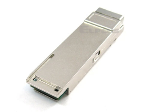
QSFP interconnect system includes the use of various data speed rate transceiver modules that plug into the receptacle edge-style connector that is inboard from the box bulkhead and under a QSFP metal shield cage. The back end of the module is flush with the box bulkhead or back-panel. The small module outboard end usually has a MPO or MXC receptacle port that provides mating connection with different types of external fiber-optic cables relative to link reach requirements. There is a very extensive variety of AOMs or Active Optical Modules, to select from relative to power consumption, cost, speed rates, reaches and photonic technologies employed.
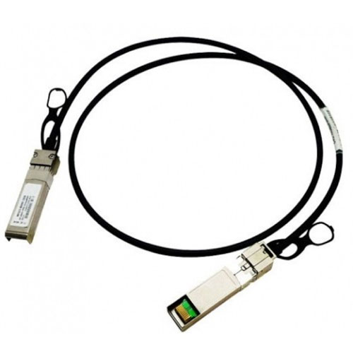
QSFP copper cables are usually constructed using eight individually shielded twin-axial transmission elements within an outer shielding layer for controlling EMI and achieving EMC regulations. The copper wire conductors and differential pair shields and system shield are carefully laser trimmed, prepped, processed and terminated with reflow soldering or laser welded to the PCB pads. Increases of higher speed data rates once caused temporary use of awkwardly large 22 AWG wire-size cables for longest length reaches. Over time, copper reach lengths requirements have been greatly reduced and some short applications now use very small 33 AWG wire size twin-axial elements, making the outer diameter cable size more acceptable. QSFP is still popular for 1, 2.5 & 5 Gbps camera network applications.

QSFP+ is the 10 Gbps per lane mainstream and current very high volume version of this connector for different signal conditioning, retiming or re-driving electrical interconnect family. Besides being specified in the 4×10 G Ethernet IEEE-802.3ak and CameraLink HS specifications, this connector chosen for 4×14 Gbps InfiniBand FDR and 4×16 Gbps FCoE standards and many other IO interface applications. To meet the increased speed rate for medium and long reaches, active copper chips were added to the cable’s PCB plug options. Some OEM systems’ house cables have had EPROM chips on board for various system management functionality such as identification while meeting closed and secured networked system requirements. Sometimes EPROM handshake inter-compatibility problems between different company products cause headaches for end-users. QSFP+ Active Optical Cables have been mostly used for 10-plus meter reaches. This is done by having an E/O engine chip on the plug PCB and terminating
QSFP+ Active Optical Cables have been mostly used for 10-plus meter reaches. This is done by having an E/O engine chip on the plug PCB and terminating optical fibered cable to the plug. See SFF-8436 QSFP+ specification for more details.
QSFP28 is the fairly new 25-32 Gbps per lane version. The past Ethernet Alliance and InfiniBand trade association plug-fest testing events were successful in working out the compliance and interoperability issues. It appears the market is using both active copper and active optical cables for most reach requirements. See the Integrators List at www.infiniband.org for various qualified suppliers. It appears a back to back receptacle connector is being developed that would have internal copper twin-axial flat cables or better substrate quality, PCB jumpers extending over the primary, but lower quality substrate main PCB. These internal QSFP28 jumpers connect back to the PCB very close to the switch chip or on top of the chip itself. IEEE802.3bj and IEEE802.3bm Ethernet standards make use of QSFP28.
QSFP56 has been the latest developing 50-56 Gbps version. It appears that this would be used for mostly active optical modules, active optical cables and maybe some very short active copper cables applications which may be more expensive and power consuming. However, this version is likely to be supplanted by the smaller, developing microQSFP56G connector. Either could support a nascent 4x50Gbps =200 Gbps Ethernet standard that may manifest later this year.
microQSFP28 is a newly released 33% smaller package size connector that enables many more ports to be on a standard 1U box bulkhead. The smaller plug PCB has made for a tighter passive/active component layout and better substrate type usage. Controlling the active chip thermal generation and heat flow through the interconnect system has been a challenge and will be more so for microQSFP56. For more info on this see the recently posted ConnectorTips microQSFP article.
Some QSFP specifications include SFF-8436, SFF-8665 and SFF-8679. These can be found at www.sffcommittee.org. The members of the SFF committee do detailed interconnect specifications for open industry standard groups as well as the originating QSFP MSA private consortium. The most popular applications are in ToR switch to Leaf servers all connected in one rack with a hydra 3 SFP+ cable legs connected into 1 QSFP+ or a hydra 3 QSFP+ legs connected together on one end with a CXP+ connector. The major threat to continued high volume QSFP related interconnect usage is the advent of inside the box, mid-board optical engines and external passive optical cables like the new MXC interconnect.
Leave a Reply
You must be logged in to post a comment.