• Skip to primary navigation
  • Skip to main content
  • Skip to primary sidebar
  • Skip to footer
  • Advertise
  • Subscribe

Connector Tips

Connector Tips has connector and electrical connector news, product highlights and and editorial coverage.

  • Products
    • board-to-board
    • cable-to-board
    • power
    • RF
    • USB
    • wire-to-board
  • Electronics
    • bonding
    • copper
    • fiber
    • gold
    • optical
    • transistor sockets
  • Markets
    • Aerospace
    • Automation
    • Automotive
    • Electrification
    • Electrical & Instrumentation
    • Medical
    • Military
    • Off-Highway
    • Oil/Gas
    • Telecom/Data
  • Learn
    • Basics/FAQs
    • eBooks/Tech Tips
    • EE Training Days
    • EE Learning Center
    • Tech Toolboxes
    • Webinars & Digital Events
  • Resources
    • Design Guide Library
    • Digital Issues
    • Engineering Diversity & Inclusion
    • LEAP Awards
    • White Papers
    • DesignFast
  • Videos
    • EE Videos
    • Teardown Videos
  • Newsletter Subscription
  • Suppliers

What does the coding mean on M12 connectors?

March 1, 2017 By Mary Gannon 1 Comment

M12 connectors are circular connectors with a 12-mm locking thread used for sensors, actuators, Fieldbus and industrial Ethernet, primarily in factory automation applications. Often with ratings ofIP65, IP68 and IP69K, they are ideal for washdown and corrosive environments.

TURCK M12 connectors coding
Image courtesy of Turck

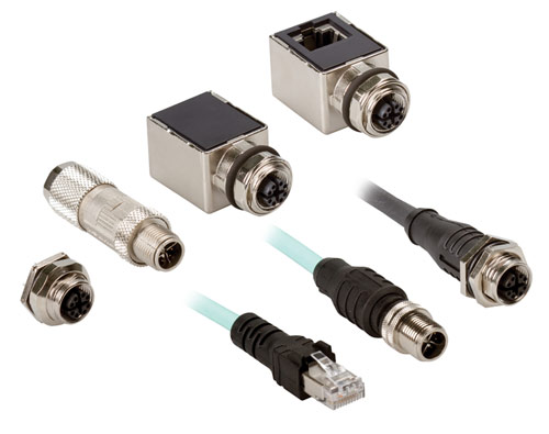
They are available with 3, 4, 5, 8 and 12 pins. While higher pin counts are not planned, other locking styles such as bayonet and push-pull are continuously under development.

The M12 family can be found in many applications such as factory automation, measurement and control, communications, food and beverage, transportation, agriculture, robotics and alternative energy.

When it comes to specific applications, users must select the right pin count. For sensors and power applications, 3 and 4 pins are required. Profinet and Ethernet use 4 and 8 pin counts. And Fieldbus, CANbus and DeviceNet primarily use 4 and 5 pin counts. Finally, specify 12 pins for signal requirements.

Several styles of coding exist in M12 connectors. This coding prevents incorrect mating on products. In addition, shielding is available in most coded M12 connectors. For example, X-coded connectors are specifically shielded by the design of their coding.

The most common types of coding include:

  • A-coded for sensors, dc power and 1 Gbit Ethernet
  • B-coded for Profibus
  • C-coded for ac power
  • D-coded for 100 Mbit Ethernet
  • X-coded for 10 Gbit Ethernet
  • S-coded for ac power (will eventually replace C-coded power parts)
  • T-coded for dc power (will eventually replace A-coded power parts)

A-, B-, D- and X-coded are most prevalent. This is because the A-, B- and D-coded connectors have been around for a long time and are some of the original M12 connectors. X-coded connectors are becoming more popular for high-speed industrial Ethernet and will eventually replace the A and D-coded parts for Ethernet applications.

A new code, K-coded, is under development for ac power, while a L-coded design will be released soon for Profinet dc power.

Special thanks to Binder USA for assistance with this article.

Filed Under: Automation, Basics, DW sync, Markets Tagged With: binder, Turck

Reader Interactions

Trackbacks

  1. designer travel tote says:
    January 27, 2022 at 8:09 pm

    designer travel tote

    What does the coding mean on M12 connectors?

    Log in to Reply

Leave a Reply Cancel reply

You must be logged in to post a comment.

Primary Sidebar

Featured Contributions

zonal architecture

Addressing zonal architecture challenges in the automotive industry

From extreme to mainstream: how industrial connectors are evolving to meet today’s harsh demands

The case for vehicle 48 V power systems

SMP3 vs. SMPS: why two standards?

mmWaves bring interconnect challenges to 5G and 6G

More Featured Contributions

EE TECH TOOLBOX

“ee
Tech Toolbox: 5G Technology
This Tech Toolbox covers the basics of 5G technology plus a story about how engineers designed and built a prototype DSL router mostly from old cellphone parts. Download this first 5G/wired/wireless communications Tech Toolbox to learn more!

EE LEARNING CENTER

EE Learning Center

RSS Current EDABoard.com discussions

  • SMPS feedback circuit
  • How to generate and use large‑signal S‑parameter (LSSP) files for PA harmonic‑balance (HB) simulations?
  • Snooping Around is All
  • ADEM III ECM — No CAN Signal & Power Supply Issue
  • IGBTs without negative gate drive

RSS Current Electro-Tech-Online.com Discussions

  • Pic18f25q10 osccon1 settings swordfish basic
  • More fun with ws2812 this time XC8 and CLC
  • Pickit 5
  • turbo jet fan - feedback appreciated.
  • I Wanna build a robot

EE ENGINEERING TRAINING DAYS

engineering
“bills
“connector
EXPAND YOUR KNOWLEDGE AND STAY CONNECTED
Get the latest info on technologies, tools and strategies for EE professionals.

Footer

EE WORLD ONLINE NETWORK

  • 5G Technology World
  • EE World Online
  • Engineers Garage
  • Analog IC Tips
  • Battery Power Tips
  • DesignFast
  • EDA Board Forums
  • Electro Tech Online Forums
  • EV Engineering
  • Microcontroller Tips
  • Sensor Tips
  • Test and Measurement Tips

Connector Tips

  • Subscribe to our newsletter
  • Advertise with us
  • Contact us
  • About us

Copyright © 2025 · WTWH Media LLC and its licensors. All rights reserved.
The material on this site may not be reproduced, distributed, transmitted, cached or otherwise used, except with the prior written permission of WTWH Media.

Privacy Policy