Servo and variable frequency drive designs depend on compact and reliable electrical connections.
Matt Hou • Sales Engineer • Dinkle International
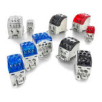
 Today’s machinery and equipment — whether built for the consumer, commercial, or industrial markets — are increasingly relying on servo and variable frequency drive (VFD) devices to provide intelligent, efficient, and precise motor control. Developers of these drives are responding to market demands with competitive designs to reduce footprint size and add specialized functions (Figure 1).
To implement these products, designers need to carefully consider all aspects of their devices, including their electrical interfaces for input power, output motor leads, and control and communication signals. Terminal blocks provide these interconnection points from field wiring to the internal printed circuit board (PCB) of the device, and designers should understand several electrical and mechanical characteristics of these components to choose the ideal parts for drives and other electrical devices.
Physical form factor
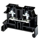
Traditionally, devices like drives were electrically installed into control panels and within equipment, and then connected to other devices using wires landed on simple screw terminal blocks, sometimes requiring fork or ring lugs to be first crimped onto the wire end. This simple methodology is time-tested, but also time consuming both for the original installation and for any subsequent service. It also introduced multiple failure points where a weak crimp, a stray wire strand, or an improperly torqued screw could lead to trouble — with extensive troubleshooting often required to find the exact point of failure.

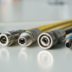
An improved option is to use connectorized plug and socket pairs. Although these parts might cost slightly more than traditional screw terminals, the ease of installation and serviceability provides many time- and cost-saving benefits over the operating lifetime. The end result is a lower life cycle cost, especially when increased reliability and uptime are taken into account. Connectorized press fasteners are easier for initial wire connections because the installer can positively orient the plug portion to the corresponding socket.
A major benefit of connectorized devices is to make it easier for panel builders to originally install the device, and for maintenance personnel to replace or service the device in the future. Connectorized devices are quicker and easier to work on, and they can be de-energized by unplugging them. By unplugging connections, technicians have better access for testing wiring.
Designers should look for connectorized press fastener pairs with:
- The necessary voltage and current characteristics
- Minimal physical footprints
- Latching/locking methods suitable for high vibration environments
- Multi-point electrical contacts for secure connections, even when subjected to vibration
- Additional support pins or structure for extra stability
- Optional screw-in provisions
- Good user ergonomics for mating and unplugging
- UL and IEC ratings
- Products subjected to rigorous testing from UL and VDE Certified Witness Test laboratories
- Metal parts with anti-corrosion and anti-aging properties to pass humidity and salt spray tests
Due to the connector pin spacing (pitch), insulation provisions, and mechanical requirements, some connectors may be unacceptably large. However, styles are available to provide secure connections in a compact form factor, with minimal space required for mounting flange and lock mechanisms as these are incorporated within the basic footprint. The electrical connection method is the next consideration.
Screw connection, higher power
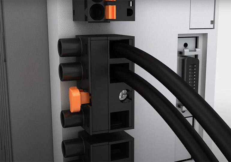
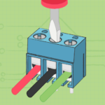
Just as standard screw connections have been common on equipment for many years, this configuration can be used in connectorized fittings (Figure 2).

Screw connections can accept stranded and solid wire, up to 10 AWG and 600 V/25 A, making them a good choice for typical servo and VFD device power connections. Proper spacing provides for effective inspection of wiring positions and integrity. Due to the nature of the screw connections, users should ensure the connector product has passed rigorous torque and rotational testing for the best reliability.
Even with the latching mechanism integral to the connector, there is an overall space savings with this connectorized wiring as compared to traditional screw terminals. Some versions also feature an additional screw used as a secondary reinforcement for maintaining the plug in the socket. On the device side, the socket must be arranged for stable connections to the PCB.
For best convenience, there is a second wire connection option.
Push-in connections, secure and efficient
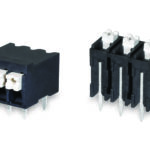
Push-in design (PID) wiring connections have gained significant attention throughout industry due to the many benefits associated with their use (Figure 3).
PID connections can accept stranded and solid wire like screw connection, but usually at smaller capacities, typically up to 14 AWG and 600 V/20 A. They are therefore suitable for some power connections, and for all signaling connections. Because a mechanical screw is not needed, these PID connectors can be even more compact than their screw-in counterparts.
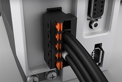
Solid wires, or stranded wires using ferrules, are installed by simply pushing them right into the spring cage, which can save up to 50% of wiring time compared with traditional screw connections. Stranded wires can be used directly if the release mechanism is operated with a small screwdriver to relief tension during wire insertion. Some terminal vendors offer a small release tool for single-handed installation of stranded wires, and for easy wire release. For best long-term reliability, designers should ensure that PID-type connectors can pass a testing regimen which includes at least 200 wiring connect and disconnect cycles.
From a physical standpoint, the spring-loaded nature of PID connectors provide excellent vibration resistance for the wire clamping mechanism and electrical contacts, while a latch and support pins securely retain the plug within the socket.
Connectors are essential for electrical reliability
Electrical connection points are just one consideration when designing electrical for hardware like servo and VFD devices. However, as the electrical interface point between the device and the outside world, they play an important role. Designers have many modern options to improve the flexibility and electrical/mechanical performance of their designs by incorporating compact and efficient connectorized components. However, it is important for these designers to understand the electrical and mechanical characteristics involved so they specify
the right products for the job.
Dinkle International
dinkle.com
Leave a Reply
You must be logged in to post a comment.