Using one wire in two very different roles is widely done, requiring some simple circuity and basic components.
Powering microphones over the audio cable
A classic engineering objective is to figure out a way to get one set of wires to provide a second function at little cost. This second part in the series looks at phantom power in more detail.
The “phantom power” technique was developed in the mid-1960s, spurred by the wider use of microphone elements such as the electret. This element provided far-superior audio signal-quality compared to the dynamic microphone but needed an applied bias power. Power was also needed for low-output microphones, which had a preamplifier located at (or within) the microphone itself. The voltage used for phantom power is usually 48 V, although some 12 and 24-V systems are in use. It eliminates the need for batteries in the microphone, which is an obvious nuisance.
Although wireless microphones are now often used by performers instead of wired ones, wired units are still popular due to their consistency, reliability, immunity to deliberate or accidental RF interference, battery issues, and more. They are also common in fixed installations such as studios where multiple microphones are in use.
Phantom power is fairly standard as defined by IEC 61938:2018 (DIN standard 45596), “Multimedia systems – Guide to the recommended characteristics of analog interfaces to achieve interoperability” and is intended for use with the XLR connector used for most audio equipment (Figure 1).
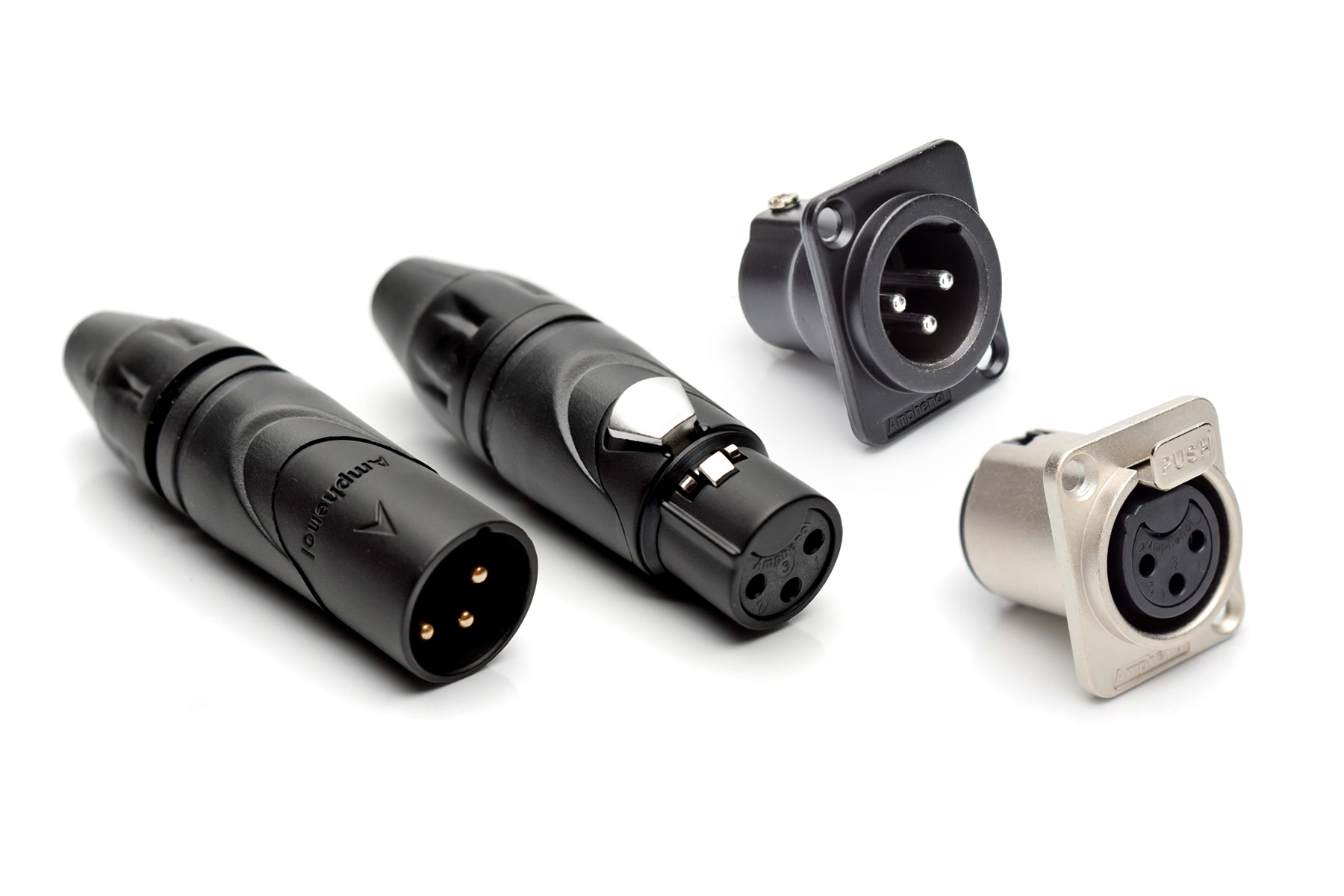
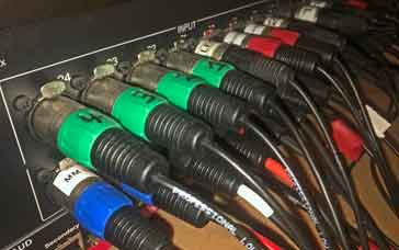
This shielded three-pin connector has the needed electrical and mechanical ruggedness but also is easily grasped for connection/disconnection due to its large body with a locking tab at the top. The XLR connector, which stands for External Line Return, was invented by James H Cannon, founder of Cannon Electric in Los Angeles, California. The connector design was modified several times in its early years and started to see widespread use by the 1950s; it is still widely used today for individual microphones and studio/performance equipment, including mixers and consoles (Figure 2).
Using phantom power, direct current is applied equally through the two signal lines of a balanced audio connector using both pins 2 and 3 of the XLR connector. The supply voltage is referenced to the ground pin of the connector (pin 1 of the connector), which is typically connected to the cable shield, a ground wire in the cable, or both.
The phantom power causes no problems for dynamic and other microphones that do not need power and is “ignored”. However, some audio consoles allow the phantom power to be shut off for the case where other equipment will be connected, for which it might be a problem. The phantom on/off switch in many consoles is labeled “P48” to signify “Phantom Power 48 volts.”
The circuitry to deliver phantom power is fairly simple. It begins with a standard 48-V AC/DC supply isolated from the AC line by a transformer for safety as part of normal supply-design architecture. (In some special cases, the 48 V is provided by batteries, so there is no transformer.) The current and power required for phantom power are modest: the supply needs to deliver up to 100 mA (under 5 W), but most modern microphones and preamplifiers need much less than that value. Only a small amount of circuitry is required in the microphone console or mixer to add this phantom power to the XLR cable and connector going to the microphone (Figure 3).
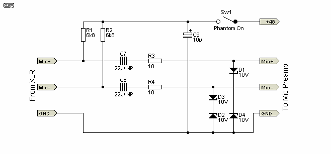
The current goes from the positive terminal of the 48 V supply (at the right), onto the microphone cable, then to the microphone XLR connector (at the left). Inside the microphone, this current is used for the microphone element (or preamplifier), and returns to the power supply via the ground lead (cable shield) of the XLR connector.
Looking at the circuit in more detail, the 48 V at the mixer or console is routed via R1 and R2 (standardized at 6.8 kΩ) from pins 2 and 3 to the power rail connection of the microphone or preamplifier. At the same time, bulk capacitor C9 (10 µF) smooths the DC. At the same time, the balanced audio single from the microphone travels back to the console via C7/R3 (22 µF/10 ohms) and C8/R4. Diodes D1 through D4 are for overvoltage protection and are not part of the phantom-power functionality. No special circuitry is needed in the microphone itself, as the microphone’s active electronics just draw on the power at pins 2 and 3, with pin 1 as the power-return ground.
The next part of this article looks at using an RF-carrying coaxial cable to also provide remote power.
Related EE Word Content
- Triple-band GNSS low-profile helical antenna features small form factor
- Surface-mount antennas cover GPS high-precision, correction bands
- DLNA Approves HomePlug AV and HD-PLC Powerline Networking for Increased Digital Home Connectivity
- The complexity of wireless receiver testing
- Gadgets: Several Decisions To Be Made Before Selecting New Headphones
- Microphone Product Family Adds Calibrated System With Phantom-Powered Preamplifier
External References
- ProSoundWeb, “A Primer On Phantom Power For Condenser Microphones”
- SweetWater, “What is Phantom Power and why do I need it?
- Electrical Engineering,” Can anyone explain Phantom Power and, specifically, how it’s used in satellite television systems?”
- Elliott Sound Products, “48V Phantom Feed Supply for Microphones”
- Instructables, “Make a Mobile Antenna to Listen to FM Radio Without Headphones”
- Learning Electronics, “Antenna Input & Audio Lineout Adaptor For Portable Radios”
- Skyworks Solutions, AN383, “Si47xx Antenna Schematic, Layout, and Design Guidelines”
- NXP Semiconductor, AN11420, “NXP GPS LNA – GPS LNA voltage supply via a coax cable
coming from the GPS receiver” - Maxim/Analog Devices, Application Note 6166, “MAX20328 Adds FM Radio Antenna Path to Smartphones with USB Type-C Interface”

Leave a Reply
You must be logged in to post a comment.