RF connectors for mmWave are shrinking to accommodate higher performance and higher densities in 5G communication networks and devices. This FAQ begins by looking at today’s 4.3-10 coaxial connectors, which were developed to solve the performance issues inherent to the previous 7-16 connectors. It then examines how the technologies unveiled in the 4.3-10 are further refined in the emerging 2.2-5, NEX10, and 1.5-3.5 RF connectors. It closes by examining how RF flex-to-board connectors are shrinking for use in handsets, drones, and other portable devices.
Smaller, simpler, and higher performance
The 4.3-10 was developed not just to be smaller. The 4.1-9.5 is a similar-sized connector and already offered a smaller alternative to the 7-16. The 4.3-10 was developed to be simpler and deliver higher performance compared with the 7-16 and 4.1-9.5 connectors. Three types of 4.3-10 male connectors are defined; torque screw, hand-tighten (sometimes called hand-screw), and push-fit; all three can mate to the universal female interface (Figure 1).
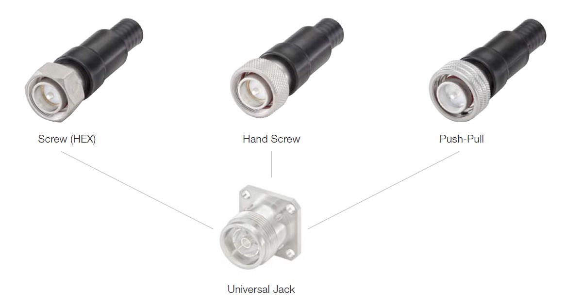
The most important technical development in 4.3-10 was the separation of the electrical and mechanical mating planes inside the connector. That separation resulted in significant performance benefits:
- It allows voltage standing wave ratio (VSWR) performance up to 6GHz and lower passive intermodulation (PIM) even when not fully torqued. Separating the electrical and mechanical planes enables the use of radial contacts that need much less force to ensure optimal communication. Since high torque is not required, screw, hand-tightened, and push-fit designs are possible without sacrificing electrical performance.
- It makes the 4.3-10 better suited for field installations since the outer body of the connector protects the electrical contacts and mating plane. This feature also prevents electrical performance from being degraded by mishandling. And 4.3/10 connectors have an IP67 rating.
- It enables higher density, lighter weight, and lower cost interconnect systems. A 4.3-10 connector fits into a 25.4mm (1 inch) flange, increasing interconnect density, and it’s up to 40% lighter than a 7-16. The connector panel for 4.3-10 connectors can have a thinner wall thickness since it is not needed to withstand high torque settings, further reducing system weight and cost.
4.3-10 connectors were developed for high-performance and high-density multi-input multi-output (MIMO) and 5G antenna arrays used in small cells and distributed antenna systems (DAS) applications. They’re especially suited to outdoor applications that need water and dust ingress protection.
Are 4.3-10 connectors really low PIM?
Yes. But that doesn’t mean that installations using these connectors are necessarily low PIM. One of the design goals for the 4.3-10 was low PIM in mobile network equipment. But PIM performance is not that simple and is certainly not controlled by a single component such as a 4.3-10 connector. The use of 4.3-10 connectors can be a necessary but not sufficient condition for a low PIM installation. Low PIM results from the interactions between many factors, including the other connected components and the implementation, materials, and manufacture of the connector interface panel and other system elements. 4.3-10 installations are not inherently low PIM but can be low PIM if the other components are properly selected and assembled.
They are still shrinking and going indoors
While the 4.3-10 standard was developed with mostly outdoor installations in mind, the emerging 2.2-5 and NEX10 mmWave connector standards target indoor and outdoor installations. RF connectors are expected to continue shrinking, with an even smaller 1.5-3.5 design being proposed. 2.2-5 RF connectors are 53% smaller than 4.3-10 and 70% smaller than 7-16. IEC 61169-66:2021 provides information and rules for preparing detailed specifications for series 2.2-5 RF coaxial connectors with quick-lock or screw coupling, characteristic impedance 50 Ω, and operating frequencies up to 6 GHz.
While smaller and lighter than the 4.3-10 series, the 2.2-5 series delivers comparable electrical and environmental capabilities. The new connector can accommodate various low loss cables up to ½”, provides an IP68 NEMA rating when mated, and can be blind mated, increasing installation flexibility.
The NEX10 interface also targets applications that need low and stable PIM, such as small cells, distributed antenna systems, in-building systems, and MIMO. NEX10 offers blind mate for panel connections. Like the 2.2-5 series, NEX10 connectors feature:
- Separation of electrical contact from the mechanical reference, supporting a low PIM regardless of the applied torque
- Robust design to prevent damage from cable movement or vibration
- Protected contact areas prevent electrical performance from being degraded by mishandling
And, like the 2.2-5, NEX10 standardization is underway, in this case as IEC 61169-71:2022 – Radio-frequency connectors – Part 71: Sectional specification for RF coaxial connectors with inner diameter of outer conductor 5.0 mm – Characteristic impedance 50 Ohms (type NEX10). Additional features of the 2.2-5 standard include:
- Performance up to 20 GHz
- Minimum flange height of 12.7 mm supports compact and lightweight modules
- A choice of screw type and push-pull connections to provide installation flexibility.
- Optional weather protection boot as a standard product
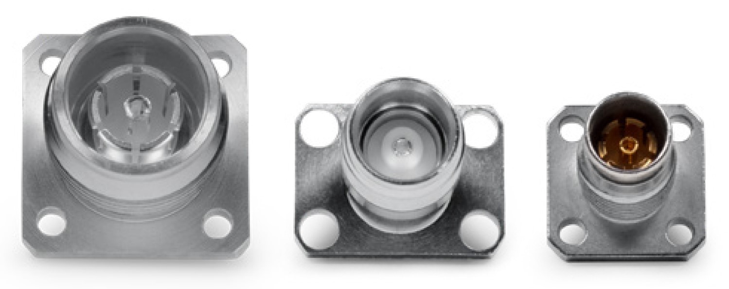
The NEX10 is more extended, thinner, and can transmit a little less power than 2.2-5. The NEX10 offers a smaller flange supporting higher density installations. While both the 2.2-5 and NEX10 connectors are still going through the standardization process, an even smaller option has been introduced, the 1.5-3.5, which is 75% smaller than the 4.3-10 (Figure 2). The 1.5-3.3 form factor is based on the SMA standard of a 12.7 mm square flange mount. These connectors are being developed for small cell applications and can support up to ¼ in. coaxial cables.
Multi coax connectors
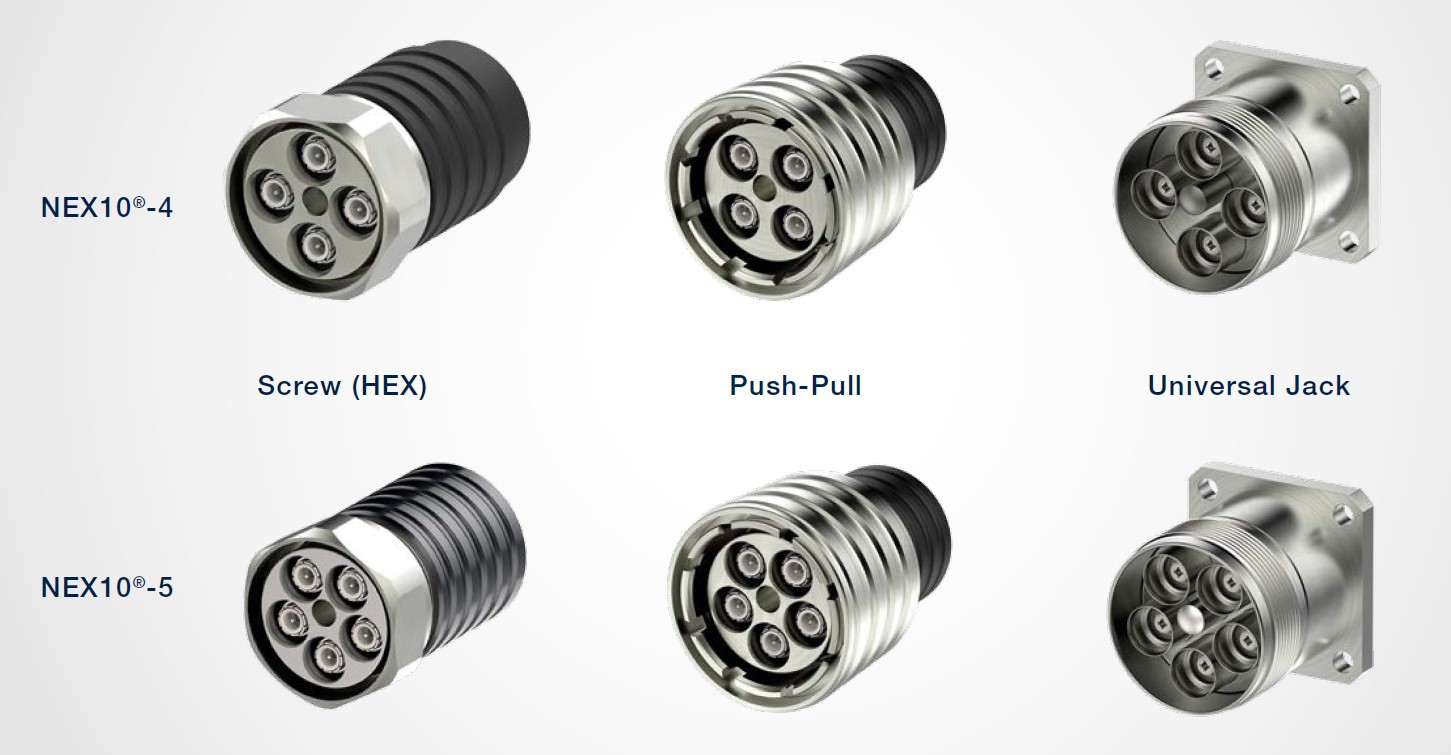
NEX10 has gone one step further in miniaturization and offers multi-coax connectors to support the need for higher interconnect densities. A NEX10 multi-coax connector is the same size as a 7-16 connector but provides 4 or 5 NEX10 interfaces (Figure 3). For very narrow applications, a push-pull version is available. Some benefits of using multi-coax connectors include
- Faster installation
- Equivalent electrical performance to single NEX10 connectors
- The smaller form factor for higher installation densities
- No swappable links eliminates installation errors
Inside handsets and drones
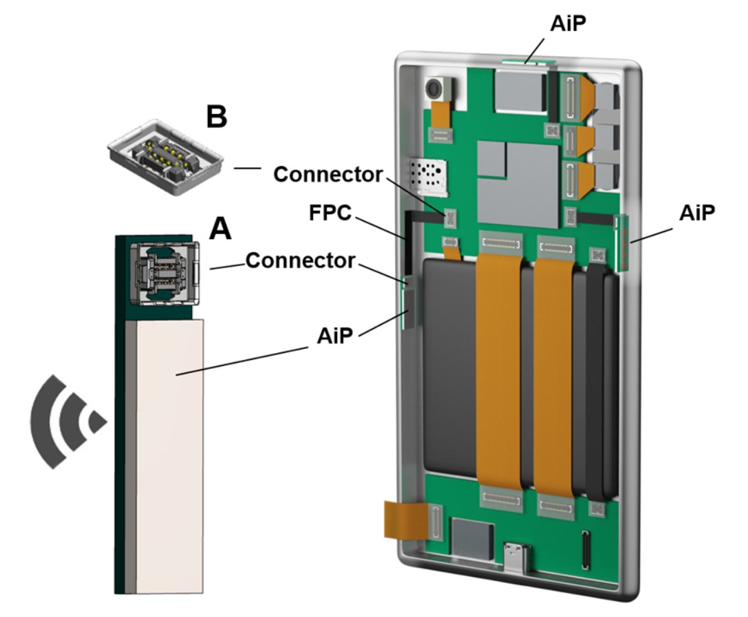
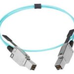
For smartphone handsets, drones, and other 5G devices, multiple antenna in package (AiP) components are arranged in different directions to compensate for the problems caused by millimeter-wave directivity (Figure 4). While that addresses the challenges with antenna directivity, it adds the challenge of integrating multiple AiPs and RF connectors in a highly constrained space. To maintain system performance, shielded connectors with high levels of signal integrity are required. To simplify the interconnect challenges, the mmWave signals are converted to a lower intermediate frequency in the AiP. That enables the use of flex-to-board connectors and low-profile vertical connectors.
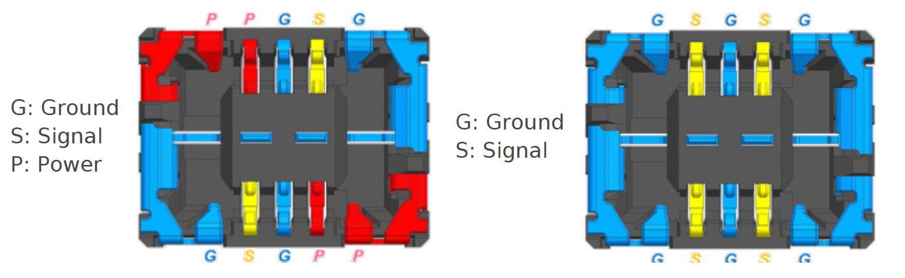
Miniature 5G mmWave RF flex-to-board connectors have been developed to address the needs of 5G mobile phone handsets, wearables, and other devices for connecting multiple antenna in package (AiP) components and the main board. These connectors are fully shielded, suppressing radiated electromagnetic interference, and use an improved contact structure for the RF terminals to ensure good transmission characteristics at mmWave frequencies. These connectors include a combination of signal and ground terminals to ensure high levels of signal integrity. In designs that need to deliver power to the AiP for signal conversion and conditioning functions, some of the pins can be used to deliver up to 1A (Figure 5). These connectors measure:
- Pitch: 0.35 mm
- Mated Height: 0.60 mm
- Mated Width: 2.30 mm
- Length (Receptacle): 3.04 mm
Summary
The shrinking of RF connectors began in earnest with the introduction of the 4.3-10 standard that separated the electrical and mechanical mating planes inside the connector, reducing PIM and making the connectors more robust for installations in the field. Subsequent generations of ever-smaller RF connectors such as 2.2-5 and NEX10 have adopted the separation of the electrical and mechanical mating functions and extended that functionality for indoor as well as outdoor installations. To further increase the density of antenna installations, the NEX10 standard includes 4- and 5-cable configurations in a single connector. If adopted, the emerging 1.5-3.5 will continue the trend of connector miniaturization for 5G small cells, DAS, and other systems. At the same time, a new class of low-profile RF connectors has emerged for use in 5G handsets, drones, and similar applications.
References
2.2-5 Series Consortium
5G mmWave RF Flex-to-Board Connectors, Molex
Fully shielded Board-to-board for 5G Millimeter-wave, Japan Aviation Electronics Industry
Low PIM Connectors and Components for Mobile Communication Applications, 4.3-10, Rosenberger
Miniature Low PIM RF Coax Connector System, NEX10, Rosenberger
NEX10 Consortium
Small Cell Connectors, Spinner


Leave a Reply
You must be logged in to post a comment.