As the demand grows for small, portable electronic processor modules in military, aerospace, and surveillance applications, so is the need for circuit-board connectors that not only fit these tight spaces but also maintain signal integrity during shock and vibration. Often, two boards may need short, flexible interconnecting wiring and/or need an output port connector (much like cell phones).
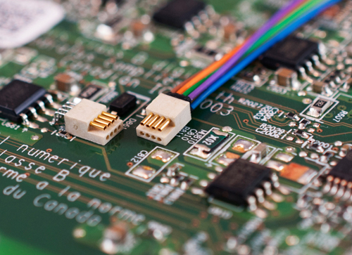 The New PZN connector from Omnetics Corp. is being adopted in a number of those areas because of the QPL qualities of the pin and sockets being used inside the connectors. These connectors can be SMT-mounted for automatically using pick-and-place assembly methods.
Pin configuration
The ultra-miniature pin/sockets used in Omnetics’ PZN connectors were chosen because they offer high signal integrity during potential high shock and vibration usage in miniature wearable electronics. In addition, keeping the total weight of the connector very low was critical, as some application-use-length is based on weight vs. battery power. This pin and socket also worked in extreme examples such as planned-crash landings of portable Unmanned Aerial Vehicles.
Designed specifically for military, space and military applications, the flex-pins feature a configuration that maintains flexibility and low-contact resistance. The cantilever spring pin uses a two-leaf design, with one end of each leaf fixed while the other floats. Pin-length and cross-sectional area are larger than most other designs, providing a higher mate-demate life and sustaining a more constant insertion and withdrawal force.
The tapered geometry ensures a gradual deflection that minimizes unnecessary high insertion forces and improves the range of intermate alignment to the socket system. Two sizes of this pin design are available from Omnetics to mate to industry standard socekts: micro (0.050 in.) and nano (0.025 in.) pitch connector technologies. The PZN design uses the nano-sized pitch.
Certified to MIL-DTL-32139 for shock and vibration testing, the pins have a minimum tensile strength of 120,000 ksi. Pins are gold-plated to ensure long-term contact integrity. Finally, the pin sizes fit MIL standards and will intermate with other standard socket designs in the micro and nano industry.
Matching electronic circuit trends
The industry has started to shift use of older Planar chip technology for analog circuits to the newer CMOS silicon technology, causing the electrical circuit demands have changed, much like the shift in automobiles to include hybrid portions of the engine.
The newer CMOS chip technologies demand much lower voltages, much lower current levels, and so can now use much smaller diameter wiring from module to module to drive their circuits. Omnetics’ PZNs are popular because they fit that trend easily and do not take a lot of space in the system.
A variety of uses
The PZN’s connector contact uses both the male and female within the same insulator design. The connector design provides self-alignment during the mating process. Shell and lead formats for SMT and other shapes are readily available with contact counts from 4 to 24 leads. Typical wiring for cable interconnection is accomplished using 32 AWG Teflon insulated multi-strand copper wire rated for up to 1 A of current.
In addition to those applications mentioned already, circuits using the new PZN connector family range from differential signal processing for digital image processing to low lever power routing to sub-circuits in modules. Probe handles, optical tools for surgery, and robotic limbs are perfect applications. PZN connectors can substantially help squeeze more interconnection into a smaller space. Custom designed miniature cable systems can include EMI shielding and or multiple sets of shielded twisted pairs to keep circuit instructions separate and prevent noise intrusion.
Omnetics Corp.
www.omnetics.com
Leave a Reply
You must be logged in to post a comment.