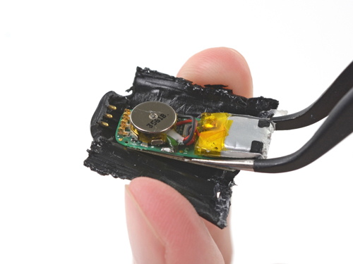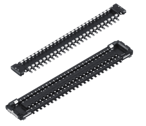
Wearable and mobile electronics are getting smaller, and that’s a big problem. Their lack of internal space makes it difficult to find electrical components that will not only fit, but also perform reliably. This difficulty can be particularly noticeable when it comes to board level connectors.
You can now source high-density connectors with terminal pitches as tight as 0.35 mm and widths down to 1.7 mm on the socket side. Just a few years ago, connectors with a similar terminal pitch would have been at least 33% larger.
This miniaturization creates a number of electrical and mechanical issues for both board-to-board and board-to-flexible printed circuit (FPC) connectors. Fortunately, you can work around the engineering constraints related to miniaturization by paying attention to connector design features. Here’s what you need to know.
Maintain key electrical properties
The small form factor of fine-pitch connectors makes it all the more difficult to meet key electrical requirements—such as protection against electromagnetic interference (EMI) and impedance matching.

Shielding—As terminal pitch narrows, it becomes much more difficult to manage EMI. Fine pitch connectors can lack the internal space for EMI shielding and ground terminals. In high-performance mobile products, radio frequency interference (RFI) between internal electric parts and the antenna circuit has been an issue because it causes severe degradation of receiver sensitivity. To avoid the degradation, we provide small, shielded board-to-board connectors with a multi-ground contact. When using this type of connector, electromagnetic noise from the connector is attenuated. Some connectors, however, do manage to strike a good balance between size and EMI reduction.
For example, Panasonic’s P4S Shield Type has a terminal pitch of just 0.4 mm and still manages to incorporate EMI shielding and ground terminals every 2.4 mm. When mated, this connector attenuates electromagnetic noise by 2.1 dB (average of 100 MHz to 3 Hz), a significant reduction that all but eliminates EMI from the connector itself. Despite the addition of the shielding features, this narrow pitch connector still takes up very little room at just 1.5 mm high and 3.80 mm wide. The P4S Shield Type is also available in 50- and 74-pin versions for even higher density connections. It also has versions for both board-to-board and board-to-FPC connections.

Impedance matching—In the growing number of applications involving high-speed data transfer, impedance matching between the board and connector helps preserve the signal integrity—by preventing signal reflection. In the past, you would typically have to trade off impedance matching and connector size. But recently, fine-pitch connectors that allow impedance matching and support high-speed data transmission standards have become more widely available.
One such connector is the Panasonic Y4BH, which is among the first impedance matched fine-pitch connector of its size. It features a 0.4-mm terminal pitch, 1.0-mm height and 3.2-mm width. The Y4BH has no fixed ground pin, which allows any contacts to be used as ground or signal. In cases where the connectors are used in high-speed differential data, it’s still best to use a GSSG pin assignment pattern for optimal performance.

Intended for high-speed data transmission, this new connector precisely matches the differential impedance of the FPC. It supports high-speed data transmission standards with characteristic impedance values of:
• 100 ohms for 6 Gb/sec, SATA 3.0, DP 1.2, HDMI 2.0
• 90 ohms for 10 Gb/sec, USB 3.0, USB 3.1
• 86 ohms for 10 Gb/sec, PCI Express 2.0,
PCI Express 3.0

optimal performance.
Make robust connections
As board-level connectors get smaller, they tend to become more delicate. Yet these connectors still need to be mechanically robust to withstand challenging conditions on the assembly line and in use. These conditions include:
• High mechanical forces—In these mobile devices, board-to-board and board-to-flex circuit connections must withstand substantial forces—from insertion forces during assembly to shock and vibration forces. The best line of defense against these forces is a connector designed with a rugged contact geometry. Panasonic’s S35 Series, for example, has a removal force of 0.215 N per pin.

• Solder rise—Low-profile, narrow pitch connectors are susceptible to damage from solder rise. The best connectors will provide an integrated nickel barrier to keep the solder in its place.
• Corrosion—Corrosive gases generated can damage connectors, ultimately shortening their life. Look for connectors with an anti-corrosion surface treatment.
• Coplanarity—Coplanarity of the connector pins directly affects solderability. On a 60-pin connector with a 0.35-mm terminal pitch, for example, coplanarity should be no better than 0.08 mm to enhance solderability.
As wearable and other space-constrained mobile electronics become more prevalent, you’ll see a continuing push toward even smaller form factors. Because many of these small devices will need to maximize signal integrity, expect to see even more efforts to enhance electrical performance and mechanical reliability of narrow pitch connectors.
Panasonic
na.industrial.panasonic.com
Tough contact construction

Panasonic narrow-pitch connectors feature a rugged contact geometry called Tough Contact and use advanced materials to maximize reliability. Tough Contact connectors are built around a metal bellows whose spring forces strike a balance between easy insertion and resistance to shock loads. The Tough Contact design also features a notched cross section to ensure a high-force, edge-to-edge contact between connector halves. This V-shaped notch has the side benefit of sealing out contamination from flux or other particulate. Tough Contact also features an integrated nickel solder barrier and a proprietary anti-corrosive treatment. Finally, these connectors also offer a coplanarity of 0.08 maximum up to 60 pins with a 0.35 mm pitch.
Optical connections between devices
Some of the same miniaturization trends affecting board-to-board and board-to-FPC connectors also come into play with device level data connections. Machine vision, medical and test-and-measurement systems are all becoming more compact. At the same time, they require fast, noise-free data transmission between peripheral sensing units and control boards. One emerging solution for these applications is the use of compact optical connectors.
The Panasonic Active Optical Connector (AOC), for example, consists of small, PCB-mounted connectors that communicate over an optical cable at distances up to 10 m.
Board-mounted optical transceivers have been available for years, but earlier models tended to be rather large in relation the AOC.
Compared to SFP Type optical connectors, the AOC technology reduces the amount of space needed on the PCB by more than 80%. The space savings result, in large part, from the integration of the connector’s optical-electrical converters into the optical cable.
In high-speed data transmission applications, optical connectors, such as the AOC, offer some compelling assembly and performance benefits over traditional wired connections:
Easy wiring and assembly. Optical connectors simplify wiring process. Connecting the AOC is as simple as plugging the optical cable to the two receptacles on the board. And unlike optical transceivers, the AOC does not need to be aligned.
High transmission speeds. AOC offers single-channel, bidirectional data transmission at speeds up to 6 Gb/sec.
Electrical isolation. Because the connection between devices is optical, the AOC provides electrical isolation, which is essential in applications that require reliable data transmission. The AOC has passed isolation voltage tests at 5.5 and 7.0 kV on 5 cm of fiber.
Reliability. With traditional optical receivers, dust can interfere with data transmission. AOC has no exposed optical connections—all optics are encapsulated within the plug and cable.

Leave a Reply
You must be logged in to post a comment.