• Skip to primary navigation
  • Skip to main content
  • Skip to primary sidebar
  • Skip to footer
  • Advertise
  • Subscribe

Connector Tips

Connector Tips has connector and electrical connector news, product highlights and and editorial coverage.

  • Products
    • board-to-board
    • cable-to-board
    • power
    • RF
    • USB
    • wire-to-board
  • Electronics
    • bonding
    • copper
    • fiber
    • gold
    • optical
    • transistor sockets
  • Markets
    • Aerospace
    • Automation
    • Automotive
    • Electrification
    • Electrical & Instrumentation
    • Medical
    • Military
    • Off-Highway
    • Oil/Gas
    • Telecom/Data
  • Learn
    • Basics/FAQs
    • eBooks/Tech Tips
    • EE Training Days
    • EE Learning Center
    • Tech Toolboxes
    • Webinars & Digital Events
  • Resources
    • Design Guide Library
    • Digital Issues
    • Engineering Diversity & Inclusion
    • LEAP Awards
    • White Papers
    • DesignFast
  • Videos
    • EE Videos
    • Teardown Videos
  • Newsletter Subscription
  • Suppliers

Press-fit PCB pins from Mill-Max are designed for plated-through holes

November 6, 2018 By Mary Gannon Leave a Comment

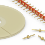
Mill-Max Manufacturing Corp., Inc. today announces four new pins specifically designed for press-fit into PCB plated-through holes, providing a secure connection while maintaining plated-through hole integrity and continuity. These new PCB pins incorporate square press-fit geometry and angled vent features making them suitable for solderless press-fit or press-fit and solder PCB termination.

Mill-Max-press-fit-PCB-pins
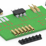
The four pins presented here are double tail header pins featuring a square press-fit shank, a round tail and a standoff body in between. When these pins are pressed into a plated through-hole the points (the major or circumscribed diameter) of the square are set or embedded in the hole while the flat sides of the feature (minor or inscribed diameter) provide relief, allowing the remainder of the plated through hole barrel to remain intact. The result is internal board layers are not disconnected when the pin is pressed in. With a properly specified hole size, the polygon shaped press-fit feature will allow the pin to be secured in the hole while maintaining continuity throughout all the layers of the PCB.

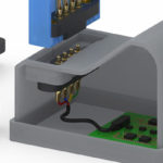
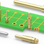
Often, these pins are used as the output terminals in applications with more demanding mechanical/electrical requirements such as power supplies, power converters, rectifiers, relays and any device subject to blind mating or rough handling. The press-fit end terminates to a board inside the device while the exposed tails are typically plugged into sockets or soldered into PCB holes by the user. In the latter case, vents located at the pin end allow soldering gasses to escape enabling better solder flow. Another common use for these pins is in board stacking applications, particularly those used in power environments. Mill-Max employs advanced machining technology to manufacture pins with exact press-fit features to suit a variety of hole sizes and assembly requirements along with precise body lengths to deliver consistent, controlled standoff heights between boards.

Mill-Max
www.mill-max.com/pr689

You may also like:

  • MillMax-PR688_1350X900
    Spring-loaded connectors from Mill-Max offered with solder-cup terminations
  • Mill-Max parallel board-to-board connectors
    Mill-Max introduces parallel board-to-board connectors

  • Low profile, removable carriers for male PCB pins and terminals
  • MillMax-Swage-Pins-interconnects
    Mill-Max launches swage mount PCB pins for interconnect applications
  • MillMax-PCB-Pins
    Press-fit PCB pins from Mill-Max are designed for plated through-holes

Filed Under: DW sync, EE sync, Featured, Products Tagged With: millmax

Reader Interactions

Leave a Reply Cancel reply

You must be logged in to post a comment.

Primary Sidebar

Featured Contributions

From extreme to mainstream: how industrial connectors are evolving to meet today’s harsh demands

The case for vehicle 48 V power systems

SMP3 vs. SMPS: why two standards?

mmWaves bring interconnect challenges to 5G and 6G

Ensuring integrity in high-performance interconnects with connector backshells

More Featured Contributions

EE TECH TOOLBOX

“ee
Tech Toolbox: Internet of Things
Explore practical strategies for minimizing attack surfaces, managing memory efficiently, and securing firmware. Download now to ensure your IoT implementations remain secure, efficient, and future-ready.

EE LEARNING CENTER

EE Learning Center

RSS Current EDABoard.com discussions

  • Why does Synopsys DC need Inverters and Buffers if my RTL only has XOR logic?
  • I/O constraint for Hold check
  • SPI speed pic18f66j15
  • GanFet power switch starts burning after 20 sec
  • RF-DC rectifier impedance matching

RSS Current Electro-Tech-Online.com Discussions

  • stud mount Schottky diodes
  • LED circuit for 1/6 scale diorama
  • Hi Guys
  • using a RTC in SF basic
  • Can I use this charger in every country?

EE ENGINEERING TRAINING DAYS

engineering
“bills
“connector
EXPAND YOUR KNOWLEDGE AND STAY CONNECTED
Get the latest info on technologies, tools and strategies for EE professionals.

Footer

EE WORLD ONLINE NETWORK

  • 5G Technology World
  • EE World Online
  • Engineers Garage
  • Analog IC Tips
  • Battery Power Tips
  • DesignFast
  • EDA Board Forums
  • Electro Tech Online Forums
  • EV Engineering
  • Microcontroller Tips
  • Sensor Tips
  • Test and Measurement Tips

Connector Tips

  • Subscribe to our newsletter
  • Advertise with us
  • Contact us
  • About us

Copyright © 2025 · WTWH Media LLC and its licensors. All rights reserved.
The material on this site may not be reproduced, distributed, transmitted, cached or otherwise used, except with the prior written permission of WTWH Media.

Privacy Policy