The variety of USB connector styles available can be confusing. But the recent release of USB 3.1 will likely speed the phase-out of some older versions and help simplify the specification of cables and connectors involved in the charging of peripherals.
Leland Teschler • Executive Editor
Engineers designing with the widely used USB standard can be excused for being a bit befuddled about nomenclature. One reason: The recently released USB 3.0 is now officially called USB 3.1 Gen 1; USB 3.1 is called USB 3.1 Gen 2. Another complicating factor is that there are about 12 different connector styles available for handling USB signals. The recent development of USB 3.0 and 3.1 standards is expected to make several of these obsolete. But until obsolescence comes, designers must be able to differentiate one USB style from another.
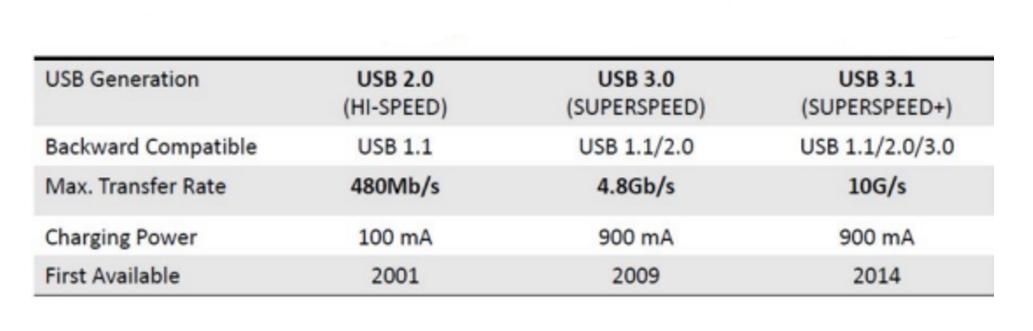 First a few basics about connection speed: USB connections in the 1990s provided two speeds, 12 and 1.5 Mbps. The USB 2.0 specification in 2000 provided a third transfer rate of 480 Mbps. The USB 3.0 standard released a few years ago moved data rates up to 450 MB/sec while retaining backward compatibility with USB 2.0. The current version of the standard, USB 3.1, extends the performance range to 1 GB/sec. Another point to note about speed is that USB 3.0 ushered in “SuperSpeed” 5 Gbps, and the USB 3.1 maximum rate of 10 Gbps is called “SuperSpeedPlus.”
USB 3.1 peripherals share bandwidth through a protocol that lets peripherals be attached, configured, used, and detached while the host and other peripherals are in operation. USB 3.1 also provides backward compatibility with USB 2.0 by means of a dual-bus architecture: One bus is a USB 2.0 bus while the other is an Enhanced SuperSpeed bus. The USB 3.1 spec uses the term Enhanced SuperSpeed as a generic adjective referring to any valid collection of USB features that were defined for the bus that runs in parallel to the USB 2.0 bus in a USB 3.1 system.
One reason USB 3.0 is becoming widely used is its capability for handling power. The 3.0 spec boosted handling power because USB 2.0’s limit of 500 mA at 5 V had become problematic for charging small electronics. Now USB 3.0 can provide 900 mA at 5V while USB 3.1 delivers more when paired with a Type-C cable, capable of delivering 5 A at 20 V.
This power handling ability has led to the use of USB 3.0 connections in several new schemes. For example, one called Quick Charge is expected to make heavy use of USB Type C connectors. Developed by Qualcomm, it aims to charge batteries in a way that is more energy efficient than ordinary trickle-charge setups.
Several suppliers provide USB connectors. “It is difficult for suppliers of USB connectors to differentiate themselves,” says CUI Inc. director of product management David Carroll. “One way we compete is by providing a broader range of mounting options, including a water-proof version we have in the works.”
However, one differentiating feature that USB specifiers should indeed watch out for are connector markings that indicate certification, says Carroll. Set up by the USB Implementers Forum, a compliance program uses a test regime at third-party testing organizations that is designed to signify a certain level of quality. Only products that pass have the right to license the USB-IF Logo.
Cables and connectors
Of course, the most visible difference between USB 2.0 and 3.0 is in the cable and connectors. USB Type-C connector and cable is reversible (the connector has no “up” side) and the cable is reversible (either end can plug into any device). The spec also provides more internal wiring than USB 3.1 strictly needs, allowing it to work with other standards such as DisplayPort.
Nevertheless, experts say for the most part, USB 2.0 devices will work on USB 3.0 hardware, and most USB 3 devices will work on USB 2.0 hardware. All USB 3.0 ports include the necessary pins and logic to process USB 2.0 signals, except perhaps for those using USB 3 connectors that are physically incompatible with their 2.0 counterparts. These include USB 3 Type-B, USB Type-C, and
USB 3 Micro-B.
The power options on USB 3.0 are more flexible. Of course, USB 2.0 peripherals could draw power from the host port and function without an external power supply. USB 3.0 includes something called the Powered B (or PoweredUSB) connector. It incorporates the standard USB comm signals plus two additional wire pairs for extra power. The Powered B male plug is only available hard-wired to devices that specifically support it.

one from another.
Standard USB B devices can connect to USB 2.0 hosts through a USB 2.0 A-to-B cable, which is compatible with USB 3.0 B ports. PoweredUSB devices, though, have a non-removable, hard-wired cable. Thus there is no chance of running a PoweredUSB via a USB 2.0 cable, nor any risk of plugging a Powered USB B device into a USB 2.0 port.
USB nomenclature
There are 12 types of USB connectors now in use. Some of these formats are expected to fall into disuse because Type C devices are better alternatives.
USB Type-A Is the classic USB connector that is essentially the same as when introduced in 1995. The A-socket connector provides a “downstream” connection intended for use solely on host controllers and hubs. It was not intended to be an “upstream” connector on a peripheral device.
Though not that common, A-A cables are used to connect USB devices with an A-style female port to a PC or another USB device, and for data transfer between two computer systems.
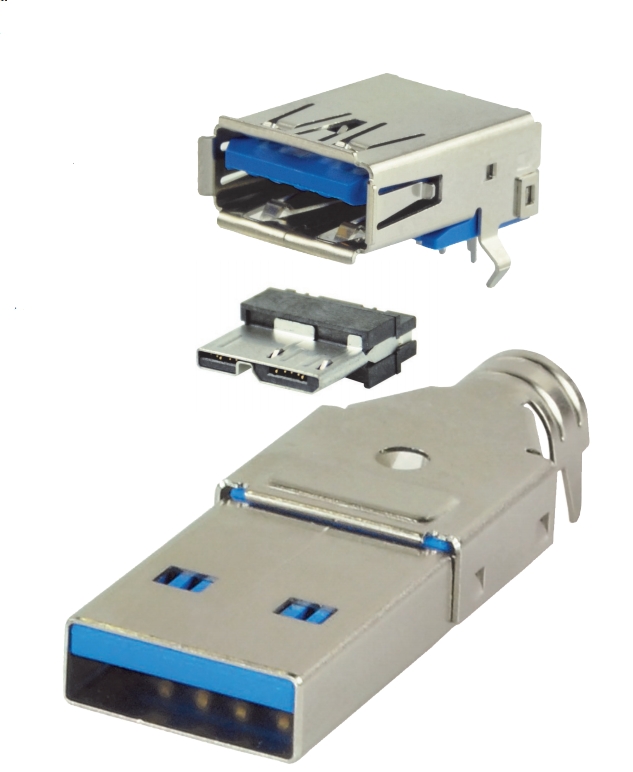
To make matters a bit complicated, there is a second A-type connector called the USB 3.0 A-type. It is nothing at all like the original USB type A connector. Known as “SuperSpeed,” this connector has additional pins that are not found in the USB 2.0 and USB 1.1 A-Type. The USB 3.0 A-Type connector is designed for USB SuperSpeed applications; however, it will carry data from slower connections and is backwards-compatible with USB 2.0 ports. USB 3.0 A connectors are often blue (Panton 300C) in color to distinguish them from previous versions.
The USB 3 Type-B connector has a squarish shape and slightly beveled corners on its top. Like the A connector, it uses the friction of the connector body to stay in place. The B-socket is an “upstream” connector only used on peripheral devices. Because of this, most USB applications require an A-B cable.
To add further confusion, there is a USB 3.0 B type connector that is different from the USB 3 Type B device. It uses an added area overhead the usual connector body to hold five new pins, a counterpart to the additional pins in the A connector. Unlike Type-A, this connector won’t work with USB 2.0 Type-B receptacles. This connector is designed to carry data and power in USB SuperSpeed applications. Cables with this connector won’t work with USB 2.0 or USB 1.1 devices. But USB 3.0 devices with this connection type can accept the older USB 2.0 and 1.1 cabling.
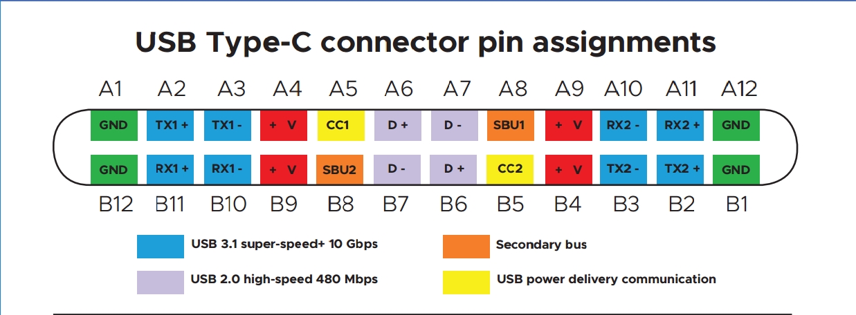
The USB Type-C (or USB-C) connector format was introduced along with the USB 3.1 spec in late 2014. Predictions are that it will eventually replace all current USB connectors. It is orientation and direction-free, and enables both SuperSpeedPlus at 10 Gbps and power transfer up to 100 W.
A USB-C cable can carry USB 3.1, USB 3.0, USB 2.0, and USB 1.1 signals. It also has built-in support for DisplayPort video and four-channel audio (speaker and microphone).
There are several flavors of what are called micro and mini USB connectors. The Micro-USB A connector can be found on newer mobile devices such as cellphones, GPS units, PDAs and digital cameras. It still supports the high-speed transfer rate of 480 Mbps. The connection is distinguished by its white-colored receptacle and a five-pin design.
Micro-USB A connectors also follow a spec called USB On-The-Go, often abbreviated USB OTG or OTG. First used in late 2001, it lets USB consumer devices such as digital audio players act as hosts, allowing the attachment of other USB devices such as USB flash drives, digital cameras, and so forth.
Similar to the Micro USB A is the Micro USB B. It handles the same 480 Mbps and has five pins as well, but its receptacle is black. It also supports On-the-Go features.
Then there is the Micro-USB AB connector. This one is designed exclusively for USB On-The-Go devices. It can accept either a Micro-USB A or Micro-USB B cable connection. This interface is distinguished by its gray-colored receptacle and five-pin connection. This connector type only exists as a receptacle for On-The-Go devices and won’t be found on a cable.
Finally, there are USB Mini connectors. The five-pin Mini-b is the most widely used style of Mini-b connector and the only one recognized by the USB standards body, USB-IF. This connector is about two-thirds the width of an A-style connector and works with USB On-The-Go.
There is also a four-pin version of the USB Mini. It is unofficial but can be found on digital cameras. It resembles the shape of a standard B-style connector with its beveled corners, but it is smaller. A similar unofficial connector is a version of the USB Mini-b made by Fuji. It mainly exists on Fuji digital cameras and has a flat rectangular shape that resembles an A style connector.
References
CUI Inc., cui.com
USB Implementers Forum, Inc., usb.org
Leave a Reply
You must be logged in to post a comment.