Terapipe I/O compression connectors and cables were developed and used in very low volume ten years ago for a special very high frequency test instrumentation network that included Vector Network Analyzer and Bit-Error-Rate Equipment. These connectors and cable assemblies had to have a very clean SI design and performance, which meant having the minimum geometry structure transition zones and profiles in the electrical signaling transmission path. The first designed connector and cable needed 20 shielded, copper differential pairs, each handling 50Gbps for a total bandwidth of 1Tbps. Thus the name Terapipe I/O was used for this custom single-direction I/O interface.
This design for Terapipe I/O compression connectors was first simulated successfully to verify signal integrity before building cable assemblies and connectors. The design started by trying to use semi-rigid, micro-twin-axial 28 AWG cable pair elements connecting in a way that required no traditional high speed I/O connector or contact components. The cable bundle was shaped into a gentle bend radius right-angle turn near one or both ends by carefully using a bend radius fixture for a very controlled bend. The electrical performance was unchanged after this process as the geometry stayed very symmetrical throughout the bend.
Some cable assemblies were just straight but still needed to have each and every pair of elements cut exactly the same length to prevent intra-pair skew as well pair to pair skew. For some secondary designs, semi-flex twin-axial pair cable elements were used that allowed more route-ability of the assembly. A method of having the twin-axial elements held precisely in a 4 x 5 array while the molding process was going was a key manufacturability goal achieved.
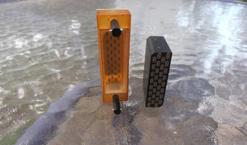
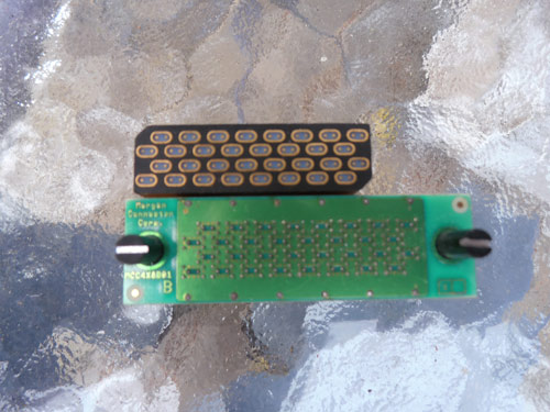
By molding an entire length of a 3 ft long multiple element cable, a fine diamond saw was used to very accurately and smoothly cut the cable straight across into many sections which were further prepped and became compression mezzanine connectors. These ft long cables were cut at 45° angles thus creating many right-angle compression receptacle connectors that were PCB mounted. So simple injection molding equipment was used to create stabile polymer housings holding the twin-axial cable elements rather bleeding edge high-speed contacts.
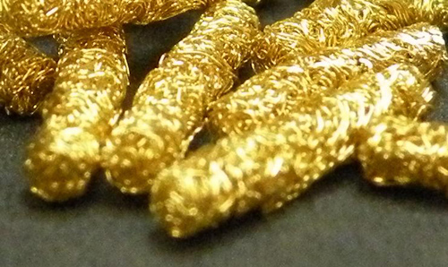
The cable’s twin-axial oval-shaped elements were then processed using two different approaches to make separable connector and cable connections. First, the oval twin-axial shield and conductor ends were cleaned. Then with special processing techniques, gold wire mesh is welded or otherwise bonded together with the shields. Then a button of the same material is attached to the conductor ends. This material has had affectionate names called Fuzz Buttons or Golden Brillo Pads. This technology has been used for high-reliability applications for decades but may be good for high-frequency digital applications. The newest, third generation of Fuzz button technology is available in much finer wire and configuration options than before.
A second approach used Shin Etsu’s Z-axis electrically transmissive polymer compression film cut into a configuration that covered the face of the connector ends. This technology allows a reasonable amount of connect and disconnect cycles. It is replaceable if needed and is a lower cost option versus Fuzz Buttons. These different interconnect solutions are both very cost competitive versus current high speed connectors. Both of these design approaches keep the SI geometry very symmetrical and continuous between PCBAs.
Maybe the technology behind Terapipe I/O compression connectors could be used for external and internal Ethernet 50GBaseCR single lane links using only very small two-pair cable assemblies that support the developing IEEE802.3cd specification. The two pairs could be configured linearly side by side or top and bottom for a square profile. A four-pair design could support 100Gbps. The developing IEEE802.3bs Ethernet standard could be supported using eight pairs for 200GBaseCR and sixteen pairs for 400GBaseCR. These prospects are definitely worth investigating.
Leave a Reply
You must be logged in to post a comment.