Many board-to-board connectors are available in three different versions to meet the needs of a broad range of system designs. This article will discuss some of the considerations that are important to making the right connector technology choice for your design.
First, let’s address the obvious:
Backplanes nearly always use press fit connectors because:
- Thick backplanes can be damaged by the thermal excursion during either wave or SMT processes that can cause the layers in the board to heat unevenly, potentially breaking plated through holes.
-
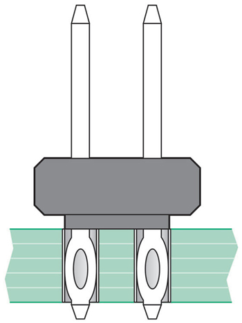
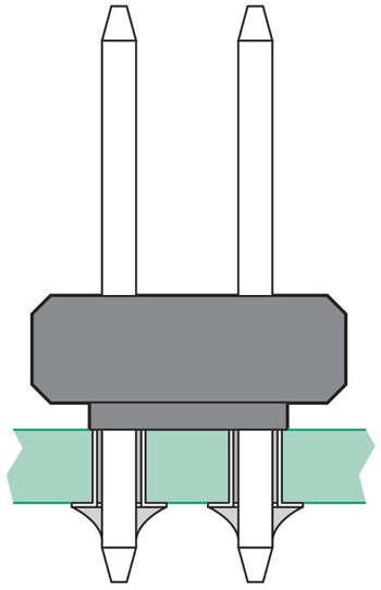
Compliant pins share plated through holes in a mid plane. Illustration courtesy of Cleaver Brinkerhoff. To avoid thermal exposure nearly every connector you might use on your backplane is available with compliant press fit pins.
- Compliant press fit pins have formed features that create gas-tight joints by acting as springs pressing outward against the barrel of the plated through hole. The plated through holes used in backplanes must be tightly controlled with greater diametric precision than other boards. In addition, the aspect ratios (length of the plated through hole relative to the diameter of the drilled hole) tend to be high. Backplanes are generally procured from a specialized supplier.
-
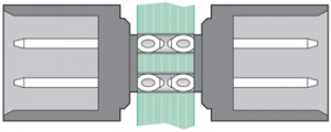
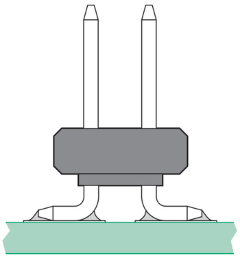
Solder tail PCB joint showing solder fillets. Illustration courtesy of Cleaver Brinkerhoff. Connectors can be pressed into the front of a backplane, into the rear, or both, with short compliant pins sharing a common hole. Because printed circuit boards (PCBs) in general have a ±10% thickness dimension, pressing short compliant pins into both sides eases system complexity by decoupling the tolerance set in front of the backplane from the tolerance set for boards or cables in the rear.
Boards that only see a wave solder process should use wave soldered connectors:
- Wave soldered joints remain the strongest possible solder joints.
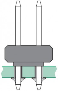
- You do need to take care, however, that the portion of the tail protruding from the bottom of the board is the right length. Therefore, connector companies offer many different solder tail options for solder tail connectors. In general terms, choose a lead length that protrudes from the board at the maximum thickness range, and does not solder bridge to the adjacent lead on a board at the minimum thickness range. Do the math. Solder filets generally create a tent at 45° from the pin tip. Adjacent tents cannot touch.
Boards that are totally SMT:
- SMT connectors on SMT boards eliminte the need for additional operations, either press fit or wave.
- One- or two-row SMT connectors are normally quite production-friendly, with the solder tails exposed for easy soldering and inspection. Connectors with more than two rows have concealed solder joints that are difficult to inspect and repair. Multi-row SMT connectors will need a solder ball or solder charge combined with very well controlled solder profile to achieve high production yields. X-ray inspection may be required.
- Signal integrity can be excellent for both SMT connectors and press fit connectors using very small plated through holes.
- Sometimes it is possible to populate SMT components in the connector shadow on the other side of the board. Using a press fit connector usually wastes the space on the other side.
Press fit connectors on SMT boards also have their place:
-
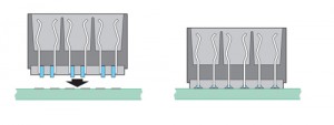
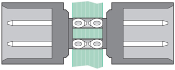
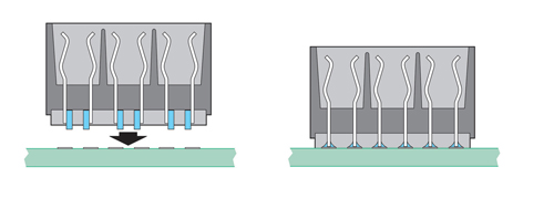
SMT connectors soldered to surface pads on boards. Illustration courtesy of Cleaver Brinkerhoff. Press fit connectors can be placed in the middle of an SMT board.
- Feed-through pins can enable stacking of multiple boards.
- Avoid issues with thermal mismatch for very large connectors.
- Create a strong right-angle connector interface that is less vulnerable to abuse during mating and unmating.
When choosing a connector technology, consider the production consequences of your choice as well as the signal integrity and mechanical robustness of your design.
Hi,
What would happen if a Press fit connector is Soldered??? Is there any technical impact for a network and communcation PCBA?? If yes, please guide me on technical aspects.
Regards,
Vimal.S
New Product Development Engineer
Avalon Technologies
Chennai.
Hi,
you don’t need to solder a press fit contact because the purpose of press fit is to avoid soldering and all the issues related to it.
If you solder a pressfit pin that has already a good contact with hole the contact itself will become stronger but nothing is gonna change in terms of functionality. But the process will be costy because you will have to deal with all the issues related to soldering.
Aun
from Punjab, Pakistan