By Ed Cady, Contributing Editor

The CXP, first called 100G Transceiver Pluggable and now Common Transceiver(X) Pluggable, product family includes connectors, cages, modules and cables. These are a part of a long-time primary type of high-speed IO interface interconnect system that includes 1 lane SFP and 4 lane QSFP. CXP is a 12-lane system broadly used to connect server, storage, switch, video and communication systems. Major market segment implementations include cloud datacenters, enterprise datacenters, HPC (high performance computing) labs, telecommunication systems and Internet provider systems.
The first generation CXP interconnect system gradually supplanted the older CX12 SFF- 8470 12×10 Gbps and SFF-8473 12×20 Gbps, another 12-lane multi-standard interconnect. Both were used for 12×10 G Ethernet LAG, Native IEEE802.3ak, Trunk 3-Link Ethernet 40 G, InfiniBand SDR 12×2.5 G and DDR 12×5 G. Ethernet 100GBaseCR10 uses 10 of the CXP 12 channels. CXP is used for few older copper wide-parallel IO interface cable links as well as newer serial IO link aggregation and multi-link trunks for Myrinet, NumaLink, RIO, RapidIO, RocketIO and several other open and proprietary interfaces.

CX12 is a two-piece copper contacted connector system while the CXP receptacle connector has stamped copper contacts but the cable plug is a dual PCB with plated pads. The two PCBs are connected using a mezzanine connector. Mated CXP connectors have cost less than the CX12 and the plug dual PCB allowed for adding active chips for achieving reach goals with higher speed data rates. Some CX12 connectors and cables are still used especially supporting an installed equipment base and can operate up to 12×20 G = 240 G.
The CXP interconnect system includes the use of various data speed rate transceiver modules that plug into the receptacle edge style connector that is inboard from the box bulkhead and under a CXP metal shield cage. The back end of the module is flush with the box bulkhead or back-panel. The CXP module outboard end usually has a MPO or MXC receptacle port that provides mating connection with different types of external fiber-optic cables relative to link reach requirements. There is an extensive variety of AOMs (active optical modules) to select from relative to power consumption, cost, speed rates, reaches and photonic technologies employed. CXP AOC (active optical cable) early applications included 100GBaseSR-12, FC 8G and SAS 6 G switch-to-switch links and uplinks using breakout or hydra cables with 12 SFP legs or three QSFP legs.
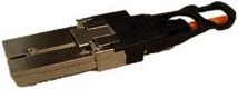
CXP copper cables are usually constructed using 24 individually shielded twin-axial transmission elements within an outer shielding layer for controlling EMI and achieving EMC regulations. The copper wire conductors and differential pair shields and system shield are carefully laser-trimmed prepped, processed and terminated with reflow soldering or laser welded to the double set of PCBs and on both pad fields. Increases of higher speed data rates once caused temporary use of awkwardly large 24-28 AWG wire-size cables for longest length reaches, usually done using three cabled legs for achieving bend radius requirements. Over time, copper reach length requirements have been greatly reduced and some short applications now use very small 30-34 AWG wire size twin-axial elements, making the outer diameter cable size more acceptable.
I will continue this discussion tomorrow, as I highlight how CXP connectors are evolving in more recent years.
Leave a Reply
You must be logged in to post a comment.