Return loss can affect insertion loss, the amount of energy that reaches a receiver.
Return loss is one of the most important S-parameter terms that characterizes a connector. You can quickly tell a good connector from a bad connector by looking at this S-parameter term. Here’s what determines good or bad.
The return loss, or S11, for single-ended S-parameters or SDD11, for differential S-parameters, is the reflected signal. Send a sine wave into an interconnect and look at what comes back out of the same port. The ratio of the reflected signal to the incident signal is the return loss.
The only way you get a reflected signal is when the incident signal encounters a change in the impedance somewhere along its path. It’s the combination of reflections from every discontinuity that contributes to the return loss at each frequency.
The reflection by itself isn’t the real problem. The real problem is the loss in transmitted signal. After all, what’s important in a channel is the signal that gets to the receiver. Some reflected signal means that less of the transmitted signal makes it to the receiver. So how much reflected signal will create a significant loss in the transmitted signal?
When an interconnect’s attenuation is low, there is a connection between the incident signal, the reflected signal, and the signal that reaches the transmitter. Most engineers think it is S11 + SS21 = 1. But remember, each S-parameter is about a voltage. There is no such thing as conservation of voltage. There is only conservation of energy.
The energy in each S-parameter is related to the square of the S-parameter, so the connection is S11² + S21² = 1, or:
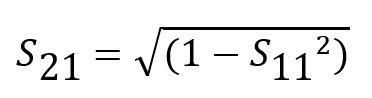
Now we can explore how much return loss will begin to affect insertion loss, the signal at the transmitter. We usually measure S11 and SS21 in decibels. Thus, we need to convert the decibel value into a magnitude, do the calculation, then convert the SS21 magnitude value back into decibels.
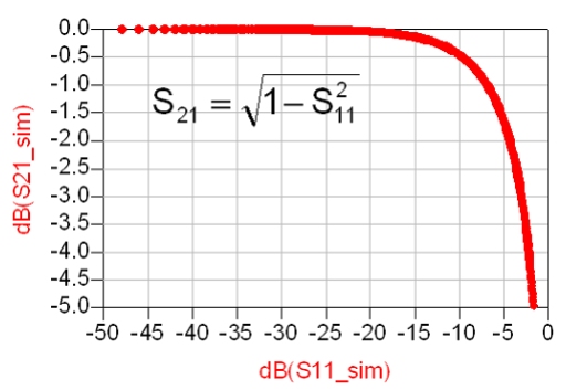
The graph in Figure 1 shows the connection between how much S11 (dB), will affect S21 (dB). It’s startling that you can have as much as -10 dB of S11 before you see even a 0.5 dB drop in S21. That explains why a typical spec on S11 can be less than about -13 dB. A larger value would begin to affect the transmitted signal. Keeping the return loss below -13 dB means the transmitted signal will not be affected by reflected signals.
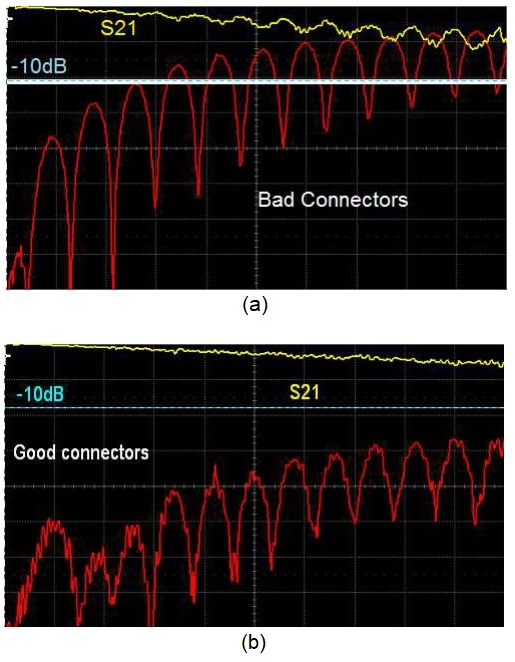
If the return loss is less than about -10 dB, we would not expect it to have any affect on the insertion loss. If, however, it reaches above -10 dB, we would expect to see an impact on the insertion loss. Figure 2 shows two examples of interconnects that are both 4-in long roughly 50 Ω microstrip transmission lines with different connectors on the ends.
When the return loss is greater than than -10 dB, the insertion loss is affected (Figure 2a). As long as the return loss is less than -10 dB, there is no impact on the insertion loss (Figure 2b).
The criterion to decide good or bad in most specs is the -13dB point. A “good” connector has a return loss below -13 dB and will have minimal impact on the insertion loss and a “bad” connector will have a return loss larger than -13 dB. It may still work in the system, but you have to do your own analysis to determine if it is still acceptable. Usually, the frequency at which a connector’s return loss exceeds -13 dB defines the bandwidth up to which it is considered “transparent.”
Related articles
- What are the functions and principles of S-parameters?
- Impedance matching and the Smith chart, Part 1
- Impedance matching and the Smith Chart, Part 2
- The difference between VSWR and the S11 reflection coefficient
- Six key considerations when selecting and integrating GHz connectors into 5G applications
Leave a Reply
You must be logged in to post a comment.