• Skip to primary navigation
  • Skip to main content
  • Skip to primary sidebar
  • Skip to footer
  • Advertise
  • Subscribe

Connector Tips

Connector Tips has connector and electrical connector news, product highlights and and editorial coverage.

  • Products
    • board-to-board
    • cable-to-board
    • power
    • RF
    • USB
    • wire-to-board
  • Electronics
    • bonding
    • copper
    • fiber
    • gold
    • optical
    • transistor sockets
  • Markets
    • Aerospace
    • Automation
    • Automotive
    • Electrification
    • Electrical & Instrumentation
    • Medical
    • Military
    • Off-Highway
    • Oil/Gas
    • Telecom/Data
  • Learn
    • Basics/FAQs
    • eBooks/Tech Tips
    • EE Training Days
    • EE Learning Center
    • Tech Toolboxes
    • Webinars & Digital Events
  • Resources
    • Design Guide Library
    • Digital Issues
    • Engineering Diversity & Inclusion
    • LEAP Awards
    • White Papers
  • Videos
    • EE Videos
    • Teardown Videos
  • Newsletter Subscription
  • Suppliers

Why is connector pitch important?

April 18, 2023 By Mary Gannon Leave a Comment

Contributed by Frances Richards

One of the most widely used connector pitches is 0.1 in., or 2.54 mm. Courtesy of Circuit Bread.
One of the most widely used connector pitches is 0.1 in., or 2.54 mm. (Image: Circuit Bread.

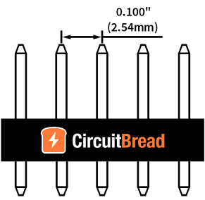
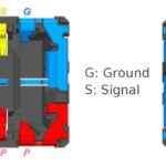
Knowing the connector pitch is vital to ensuring compatibility with the wire or cable being connected. When designing a circuit or purchasing either connectors or cables, the connector pitch must be specified to ensure a proper connection. First, let’s define pitch: A connector’s pitch refers to the distance measured from the center of one pin to the center of the next pin. Although it should be fairly straightforward, mating a connector to its other half (i.e., the wire or cable) can sometimes be confusing due to standards and descriptive terms being used interchangeably — or incorrectly.

The pitch of a header is measured from the center of one pin to the next (A). One can also measure from the outside edge of the first pin to the inside edge of the last pin (B), where A = B/(C-1). C refers to the number of pins. Source: KCR.

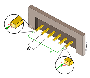
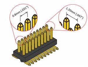
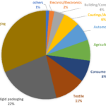
Two of the most widely used connector pitches include 0.1 in. (2.54 mm) and 0.05 in. (1.27 mm). Other commonly used pitches include 1.20 mm, 1.25 mm, 1.50 mm, 6 mm, 10 mm, 0.3 in., and 0.4 in. Many other specialized pitches are also available and can be similar in size, which is why it is extremely important to know the exact size being used. Datasheets and catalogs are helpful in selecting the right pitch. Finally, keep in mind another measurement that must be checked if there are multiple rows of contacts: The pitch between contacts in each row may be different from the pitch between rows. These two values are sometimes the same, but because they may vary, be sure to verify this distance for connectors that feature more than one row.

Schematic shows pitch measurement from contact to contact and between rows. Note that the pitch between contacts in each row and the pitch between rows are different. Although these values are sometimes the same, they must always be verified for connectors with more than one row.

You may also like:


  • Rotary slip ring connectors — what are they used for? 

  • How can connector sustainability be improved?

  • How high pin-count socket connectors are supporting new processor-chip applications

  • How the terabit class of pluggable cables and connectors is…

  • How are RF connectors shrinking for mmWave systems?

Filed Under: Basics, DW sync, EE sync, FAQ, Featured Tagged With: faq

Reader Interactions

Leave a Reply Cancel reply

You must be logged in to post a comment.

Primary Sidebar

Featured Contributions

Connections get optics and ASICs closer together

Beyond the datasheet: how digital tools are reshaping connector engineering

zonal architecture

Addressing zonal architecture challenges in the automotive industry

From extreme to mainstream: how industrial connectors are evolving to meet today’s harsh demands

The case for vehicle 48 V power systems

More Featured Contributions

EE TECH TOOLBOX

“ee
Tech Toolbox: Electronic Design Automation
This Tech ToolBox helps to clear the path to faster time-to-market by digging into AI-enhanced design, hardware-assisted verification, parasitic extractions, PCB-to-harness integration, and more.

EE LEARNING CENTER

EE Learning Center

RSS Current EDABoard.com discussions

RSS Current Electro-Tech-Online.com Discussions

  • Lifetime of components
  • Op amp gain
  • Circuit sensitivity
  • Multiple photodiodes for single ADC read
  • resonance causes peak in transfer function question

EE ENGINEERING TRAINING DAYS

engineering
“bills
“connector
EXPAND YOUR KNOWLEDGE AND STAY CONNECTED
Get the latest info on technologies, tools and strategies for EE professionals.

Footer

EE WORLD ONLINE NETWORK

  • 5G Technology World
  • EE World Online
  • Engineers Garage
  • Analog IC Tips
  • Battery Power Tips
  • EDA Board Forums
  • Electro Tech Online Forums
  • EV Engineering
  • Microcontroller Tips
  • Sensor Tips
  • Test and Measurement Tips

Connector Tips

  • Subscribe to our newsletter
  • Advertise with us
  • Contact us
  • About us

Copyright © 2026 · WTWH Media LLC and its licensors. All rights reserved.
The material on this site may not be reproduced, distributed, transmitted, cached or otherwise used, except with the prior written permission of WTWH Media.

Privacy Policy