In my last post, I wrote about the Bendix—Amphenol Bristle Brush connectors that had mating forces of 1.5 oz per contact. (To compare, most dual beam contact designs have mating forces in the range of 5 oz per contact.) High mating forces can be a problem for many connector designs, including IO connectors that are frequently mated and unmated, test sockets that mate hundreds or thousands of times per day, and especially for high pin count connectors. Many system designs can really benefit from using connectors designed to mate with zero insertion force.

In the 1970s connectors started to appear with features to enable ZIF (Zero Insertion Force). The principal for most of these connectors was similar. Contacts are arranged so that the plastic bodies can fully engage without the contacts touching, eliminating mating friction and associated wear. After the housings are mated, a cam is rotated, moving the contacts so that they fully mate with the specified normal force. Instead of a frictional mating force, the cam—typically a quarter or half-turn arrangement—is moved into position by rotating a handle. This can be accomplished by turning a handle like a doorknob, or by a screwdriver to keep the hardware small.
The ZIF concept has several advantages:
- Minimal mating wears, since there is little or no frictional rubbing between mating contacts.
- High mating cycle life is easy with ZIF connectors because they have no frictional mating wear.
- Frequently, the engagement handle can be activated with one hand, making it handy for locations where it is difficult to access with two hands or tools.
- The handle for the ZIF mechanism can do double-duty by mating signal contacts inside a metal housing with suitable EMI containment shielding minimizing or eliminating electrical interference
There are some disadvantages as well:
- Minimal mating wipe requires clean contacts with no insulating films in the mating area. You want to use ZIF connectors in clean, indoor environments.
- ZIF designs with cams are bulkier and the torsional force to activate the cams increases with the number of contacts and can require a large lever.
- Normally ZIF connectors use single beam contacts, mating on one side of the mating surface. Conventional cable IO solutions most often use redundant dual-beam contacts to ensure high reliability during vibration, shock or adverse environments. ZIF solutions are less suitable for these applications.
Typical applications for ZIF cable connectors include:
- Probe connections for Ultrasound systems where probes are frequently changed during the day for different exams
- Many applications requiring frequent mating in the industrial, test and automotive manufacturing market segments
So, if you have an application requiring frequent mating and unmating of cables, consider the ZIF solution as a candidate. The medical applications are the most important, but similar requirements exist for any equipment that needs frequent reconfiguration. Think of test equipment, especially on assembly lines that must test a wide variety of products, each having a special test head connected to the tester with a common ZIF interface. Entertainment equipment is frequently configured for a specific stage or act, then reconfigured for the next act or next performance. ZIF connectors offer cycle life exceeding 20,000 mating cycles, making them extremely useful for these applications.
Another important application of ZIF is for test sockets, especially for those testing large pin grid arrays. The ZIF arrangement allows easy plugging of the multipin array without stressing the often ceramic substrate. The combination of zero mating force with very high cycle life requirements made ZIF ideal for testing pin grid array semiconductor devices and multi-chip modules. ZIF sockets normally work with a two-piece plastic housing. One piece affixes the contacts to the PCB and the second piece is cam activated with a lever or screw fitting to close the contact beam after the package under test is fully inserted. In some cases, this ZIF socket is also used in producing products to allow field replacement of fragile multipin arrays. Click on the illustration above to see an animation of this action. Today, pin grid array semiconductors packages are quickly migrating to pad grid arrays that require other solutions, usually Z-axis compression.

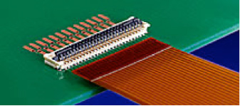
The ZIF approach is also often chosen for connectors mating flat flexible cables to PC boards. In this case, the motivation is to make the connector as low profile as possible. The assembly operator opens the top of the connector, inserts the flat cable, then snaps the door closed on the top of the connector, generating the normal force needed for a reliable connection. This low profile connector design is well suited for laptops, tablets, and other handheld devices, especially for the flex circuits leading to displays, keyboards, and switches.
ZIF designs remain quite popular today, mostly for the cable applications that require very high numbers of mating cycles. Test applications prefer ZIF approaches because they do not damage the device under test, especially important for high pin count devices.
May the ZIF be with you. (Please forgive me. I could not resist the Star Wars reference.)

Revenge of the ZIF should have been the name of the article.