I have great sympathy for the design engineer who must rummage through the mass of information found on connector sites to find the right connector for his or her application. Inevitably you eventually get through the configuration issues (number of pins, basic connector type, and key dimensions) to arrive at the page that has the specifications. At this point, one needs to understand how to break the code to understand what is being specified and why it is important. That is the discussion today.
Connector specifications cover two general areas:
- Electrical performance including current carrying capacity, impedance, voltage, etc.
- Qualification specs like RoHS , ELV, and UL
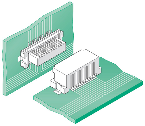
To keep this discussion manageable, I will focus on board-to-board connectors. These are the types used inside electronic boxes to connect boards together. Spec details you find for these types of connectors are representative of what you will find for connectors used in telecom, instrumentation, and computing segments. (Connectors for more severe environments in automotive and aerospace and high power have additional specs that we can cover later. I am also limiting this discussion to dc signal connectors used in digital systems. )
![]() Let’s start with the electrical specs:
Let’s start with the electrical specs:
- Current carrying capacity: Digital systems generally use milliampere current levels. The current carrying capacity is seldom dictated by the connector, but by the width and thickness of the traces on the printed circuit board.
- Voltage: Digital systems today generally use voltage levels less than 5 V to allow for fast signal switching, high-density circuits, and simple layout. Almost all connectors easily handle this low voltage.
- Impedance: Most digital systems today use 100 ohm differential signaling. Chips, connectors, and boards have all been designed for 100-ohm impedance, which helps to avoid impedance discontinuities that reduce the quality of the signals. About a decade ago, Intel started developing chips that want to see 85 ohm signals, so recently you will find 85 ohm connectors as an option. Work with your system architect who chooses the system impedance and make sure that all the connectors in the signal path meet this impedance range.
Now we’ll look at qualification specifications:
 RoHS (Restriction of Use of Hazardous Substances): RoHS compliant connectors are certified to not have lead, cadmium, or several other hazardous materials that are suspected of causing cancer. You want to use RoHS in any design you can. (Some military and aerospace applications still require lead, but systems for those markets will clearly designate this.) The default is to use RoHS.
- ELV compliant: Similar to RoHS, but specifically specified for vehicles in the European Union. Basically, they want to make sure your car can be recycled without emitting these carcinogens. If you have RoHS covered, ELV goes with it.
- Lead free: Basically, to meet RoHS requirements, manufacturers needed to remove the lead from the plating and any solder used to apply the connectors. The net effect is that the temperature used to solder the connectors needed to increase. Common tin lead solder melts at ~183°C. Common lead free alternatives are in the 227° temp range for reflow so that the connector plastic needs to withstand this higher temperature. If you use parts specified for lead free, you are safe.
- UL: This is a certification for flammability, an important factor should the system ever catch fire. In general terms, if you choose connectors using UL94 V-0 materials, you will meet the flammability requirements for systems used in telecom and data centers or similar environments. (V-1 and V-2 are more flammable than V-0.)

I hope this over simplification of connector specifications will enable you to move quickly on to the more important aspects of your design.
Leave a Reply
You must be logged in to post a comment.