It only takes 3 µA of current to fail an EMC test; a connector can produce that much.
When it comes to reducing EMI problems, most coax cables behave the same. They are all just as good antennas for common currents to radiate and fail an FCC certification-type test. It’s not the cable that is the chief source of EMC test failures; it’s usually the connector.
If there were any net current, or common current on a cable, to return through the stray fringe fields between the entire cable and the floor, back to the chassis, it would radiate. In the most sensitive FCC part 15 test condition — for 88 MHz and below — in a class B test, the largest acceptable far field at 3 m from the product is 100 µV/m. This is an important number to remember.
This means that if there is a larger field at 3 m from the product than 100 µV/m, at 88 MHz, within the 120 kHz bandwidth of the FCC test, the product will fail EMC certification and not be allowed for sale in the US. Other countries have similar certification requirements.
When the radiation source is from common currents on external cables such as those that connect to peripherals, using a “better” cable often has no impact on the radiated emissions. That’s because the common currents are flowing on the shield of the cable. Remarkably, it only takes 3 µA of common current flowing on the shield of a cable, 1m long, to cause an FCC class B failure. This is another really important number to remember, and it’s a tiny amount of current.
The most important driving voltage for these common currents that causes EMC failures is ground bounce in the connector attaching the cable to the chassis. Ground bounce is the voltage generated between two regions of the return path due to a changing current flowing through the total inductance of the return path. The total inductance of the return path is related to the total number of field lines around the conductor per amp of current flowing through it.
When the dI/dt of the return current flows through the total inductance of the connector, it generates a voltage, and this voltage between the chassis and the cable’s shield drives the common currents on the cable, resulting in an EMC failure. This is illustrated in the figure.
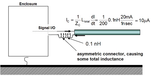
A coax cable will have no ground bounce because no external magnetic field is around it. The signal current generates an external magnetic field composed of circular rings of field lines circulating in one direction. If symmetrical about the signal path, the return current generates identical rings of magnetic field around the cable but circulating in the opposite direction. These two sets of magnetic field lines exactly cancel out, and there is no external magnetic field.
But suppose the return current is not perfectly symmetrical with the signal current at the connector. Maybe there is a pigtail, maybe the clamshell is not well-metalized, or maybe the connector only makes contact at one or two points to the chassis. Any asymmetry will mean the magnetic field lines from the signal current and return current will not perfectly cancel out. There will be some net magnetic field lines, resulting in some total inductance of the return path.
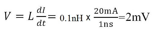
In a typical 50 Ω coax cable, with a 1 V signal having a 1 ns rise time, the signal and return current is about 1 V/50 Ω = 20 mA. Even if the asymmetry is so slight as to generate only 0.1nH of total inductance around the return path of the connector, the ground bounce voltage generated would be:
 If the impedance the common current sees returning through all those fringe field lines is about 200 Ω, this 2 mV of ground bounce voltage will drive I = 2 mV/200 Ω = 10 µA. Is this a lot or a little?
Remember, failing an EMC certification test only takes 3 µA of common current. This ground bounce-driven current in the cable shield will cause an EMC failure.
Is it any wonder it’s often a challenge to pass an EMC certification test? If you know an EMC engineer who has helped you pass a certification test, take that engineer out to lunch and say thanks!
Leave a Reply
You must be logged in to post a comment.