USB4 represents a significant change from past standards from the USB Implementers Forum (USB-IF). It is based on the Thunderbolt 3 protocol. Support of Thunderbolt 3 interoperability is required on all ports for USB4 docks, for downward-facing ports on hubs, and is optional for USB4 hosts and peripheral devices. Like Thunderbolt, USB4 allows tunneling of DisplayPort and PCI Express.
USB4 devices must support a nominal data rate of 20 Gbit/s and can support up to 40 Gbit/s. However, given the ability to use tunneling, the nominal 20 Gbit/s data rate can result in higher effective throughput in USB4, compared with USB 3.2, when sending mixed data. USB4 specifies a method whereby multiple end device types can dynamically share a single high-speed link that optimizes data transfer by type and application.
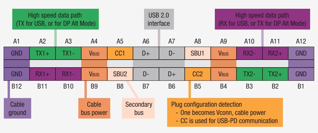
USB4 requires Type-C connectors
USB4 requires USB Type-C connectors, and for power delivery (PD), it requires the support of USB PD. USB PD provides up to 20V, 5A, and 100W for charging and other uses, including expanded data transfer capabilities. The intelligent and flexible system-level power management capabilities of USB PD support bidirectional power that can switch direction in real-time and makes possible Type-C support for other standards such as DisplayPort, HDMI, or PCI Express, through the ALT mode. ALT modes reconfigure the connector to:
- Repurpose pins to support another bus
- Change the mode of operation of a bus
- Enable sideband signals
- Change signal conditioning type or direction
Configuration channel (CC) pins are used to implement many of the UBS PD functions. Downstream facing ports (DFPs) and upstream facing ports (UFPs) each have a CC1 and CC2 pin. These pins connect to the VCON and CC lines of the Type-C cable. Both CC1 and CC2 support both the CC and the VCONN functions.
Previous USB specifications used power lines for device-to-device communications; the use of the CC pins makes the communications more reliable, adding support for time-critical operations such as fast role swapping described below. The CC communication in the newest USB PD specification supports IEC-63002-compliant communication between sources and devices.
Pull-up and pull-down resistors are attached to the CC pins. The resistors are used on DFPs and UFPs and within electronically marked (E-marked) active cables and are used for:
- Detection of cable attachment
- Detection of cable orientation
- Advertisement of the power capabilities

VCONN is a 5 V 1 W power supply that powers the IC in an E-marked Type-C cable. The E-mark IC contains configuration information for the cable, including its current rating (3A or 5A), USB specification level (USB 2.0 or USB 3.1, Gen 1 or Gen 2), and vendor identification (XID).
After cable recognition, the power sourcing device and the connected device share biphase marked coding (BMC) messages over the CC1 / CC2 lines to negotiate power needs. Power consumers request one of the defined power profiles in the USB PD specification. USB PD in the power provider dynamically manages power allocations, adjusting the voltage and current, and sets power provider or power consumer roles for all connected devices.

Bidirectional and flexible charging is a new feature made possible by USB PD’s dynamic control of higher voltages and currents. Devices can request a higher voltage when they are charging using CC1 / CC2 lines. When a device is being charged, all other connected devices renegotiate their power requirements. Devices can also renegotiate power if another device needs additional power. USB PD’s bidirectional and flexible power delivery capabilities make it possible to supply varying power levels to multiple devices and optimize battery charging.
Programmable power for higher efficiencies
Further enhancing USB PD performance under USB4 is the programmable power supply (PPS) capability that enables small step changes in voltage and current. If a power consumer is connected to a PPS capable power source, it can request changes in the power delivered by the source. Using PPS can enable fast charging of lithium-ion batteries and increase over system power efficiency.
PPS was not included in earlier USB PD specifications. In systems without PPS, designers would set the power-consuming system to request a higher voltage from the source and use a dc/dc converter to step down the voltage supplied to the battery. By adding a power conversion step in the power consumption, that approach reduced overall efficiencies. PPS reduces losses by allowing the supply side to make incremental adjustments in the voltage delivered to provide a more optimal charging solution.
Fast role swap
Fast role swap (FRS) is another new feature of the latest version of the USB-C PD specification. FRS is designed to lower the risk of data loss for USB peripherals in the event of unexpected removal of a power cable from a hub or dock. FRS maintains power to USB-powered devices when the hub they are attached to loses power. FRS involves devices switching between sink and source operation, significantly increasing USB battery charging effectiveness and reliability.
Consider a scenario where a UBP-C PD device is charging a battery, the device is the source, and the battery is the sink. Somehow, possibly accidentally, the power to the device is cut off. FRS enables the battery to become the source and the other device to become the sink, maintaining uninterrupted operation (FRS is implemented within 150μs).
FRS supports not only charging but also uninterrupted data communications. While the power sourcing relation changes, data communication flows in a single direction without interruption, preserving system operation and preventing glitches.
USB Type-C authentication
A major extension added by USB PD 3.0 is Type-C Authentication (C-AUTH). The moment a connection is made, C-AUTH confirms the authenticity of a USB device, cable, or charger to ensure that no inappropriate power or data is transferred. Unsafe USB chargers and devices can negatively affect the performance of connected systems.
C-AUTH is part of the USB-C certification testing procedures. It includes support for authentication over either USB data bus or the CC channels, 128-bit security, and is based on internationally accepted cryptographic methods relating to certificate formats, digital signaling, hash, and random number generation.
Each manufacturer needs to apply to the USB Implementers Forum to get XIDs for its products. The initiator reads its responders’ XIDs along with other electronic certification data during the USB Type-C Authentication process. An external database (white list) that includes each XID and its related compliance test status is part of the compliance infrastructure. The initiator checks the white lists to confirm that the responder’s XID is listed after being authenticated. If the XID is on the white list, the initiator can be confident that the responder has passed compliance testing.
USB PD safety and protection
Extending USB’s power delivery capabilities up to 100W increases the hazards associated with defective or substandard (counterfeit) devices. The new USB PD standard has added provisions to minimize the risk of accidents caused by defects or product misrepresentations and protect users.
Under normal operation, with a USB-compliant cable and equipment, the PD power rules ensure that the charging and other power parameters are set within acceptable limits of voltage and current. Even with compliant cables and devices, damage to a cable or connector can lead to operating errors, device damage, or even cause a potential fire hazard.
Problems can take the form of overvoltage, over current, or over-temperature situations. The latest USB PD standard includes provisions for overvoltage protection, overcurrent protection, and over-temperature protection at both the source and sink sides. Power must be reduced or shut down when any unsafe operating conditions are detected.
Summary
USB4 represents a significant change from past standards from the USB-IF. USB4 is based on the Thunderbolt 3 protocol. Thunderbolt 3 interoperability is required on all ports for USB4 docks; it is required for downward-facing ports on hubs and is optional for USB4 hosts and peripheral devices. Like Thunderbolt, USB4 allows tunneling of DisplayPort and PCI Express. USB4 requires USB Type-C connectors, and for power delivery (PD), it requires the support of USB PD.
References
How to Test USB Power Delivery Over Type-C, Keysight Technologies
Type-C™ CC and VCONN Signals, Microchip Technologies
USB Charger (USB Power Delivery), USB Implementers Forum
USB-IF Compliance, USB Implementers Forum


Leave a Reply
You must be logged in to post a comment.