The five basic connector contact termination styles include solder, press-fit, clamp, crimp, and insulation displacement (IDC). In some cases, there are variations.
This FAQ focuses on the termination of electrical signals, not fiber optic termination styles. Selecting the best termination style is important since the terminations provide stable electrical and mechanical connections and need to meet the assembly needs of the application.
The two most used solder termination styles are through-hole technology (THT) and surface-mount technology (SMT). THT relies on wave soldering. While wave soldering can be highly automated, placing the connector pins through the holes can be a manual process unless more complex robotic placement can be justified. THT can result in greater mechanical strength than SMT, especially for lateral forces. As a result, THT devices are often favored in safety- or mission-critical applications like some military and aerospace systems.
In some instances, using a connector that’s available with both THT and SMT terminations can be advantageous. THT devices can more readily support repairs or reworking using hand-soldering tools that can be desirable during development and prototyping. When the design is finalized, SMT connectors can support higher levels of automated assembly and reduce production costs.
There’s a third soldering option
A third way to implement solder terminations is pin-in-paste (PIP) or hole reflow (THR). It’s been called a “bridging” technology between THT and SMT (Figure 1). PIP uses through holes like THT, and the solder paste is printed like SMT. In this case, the solder paste is printed into the through holes in the printed circuit board (PCB).

PIP combines the benefits of the two alternatives, including the preapplication of the solder to ensure proper coverage like SMT and stronger joints since the pins go through the PCB like THT. However, there are additional considerations when implementing PIP terminations:
- While the soldering process is like SMT, the process settings are especially critical. If the oven is not set properly, the solder can drain out through the bottom of the holes.
- When implementing PIP, a reflow oven is used, and the entire connector is exposed to higher heat, which requires the use of plastics with higher melting temperatures for the connector body.
Press-fit
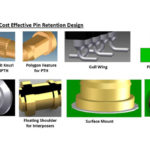
Press-fit terminations (PFTs) use through holes but don’t use solder. The pins on the connector have a “compliant” section that collapses slightly when forced into the plated holes. The material in the compliant sections has enough spring to form a gas-tight connection. The connector body must be robust enough to withstand the force needed to drive the pins into the plated holes, which can limit this technology to connectors with a limited number of pins. Another challenge with press-fit is the need for PCBs with tighter tolerances for the holes, and that increases costs. So, while PFTs don’t require solder and minimize the exposure of sensitive components to high temperatures, they are not commonly used with connectors.
Clamp
Clamp terminations employ striped wires inserted into the connector held in place with a clamp that can be implemented with a screwdriver or an internal locking mechanism. These terminations can provide high vibration resistance and low voltage drops. Clamp terminations don’t require specialized tools and are often used instead of crimp terminations in applications like alternative energy systems, energy storage, robotics, and other industrial machines.

Crimp
Crimp terminations are implemented using dedicated tools that compress the metal contact around the wire to achieve a solid electrical connection and provide corrosion resistance. Once the crimp termination has been completed, the contact is inserted into the connector housing. Crimp terminations can be highly automated and support higher contact densities than clamp terminations. They are suitable for use in harsh industrial and outdoor environments. The barrel contacts into which the wire is inserted can be fabricated with stamping or machining processes.
IDC
IDC terminations don’t require that the wire be stripped before the connection is made, and they don’t require specialized tools (Figure 2). Instead, one or more sharp points inside the connector penetrate the insulation layer, forming a gas-tight contact as the wire is inserted. IDC terminations are suited to automation and can be used with stranded or solid wires and ribbon cables. Terminating ribbon cables in computer equipment is a common application of IDC technology.
References
Selecting the Best Connector Termination Method, Harwin
What are Connector Contact Termination Types?, Northern Connector
What Are the Different Types of Circular Connector Terminations?, Amissiontech


Leave a Reply
You must be logged in to post a comment.