• Skip to primary navigation
  • Skip to main content
  • Skip to primary sidebar
  • Skip to footer
  • Advertise
  • Subscribe

Connector Tips

Connector Tips has connector and electrical connector news, product highlights and and editorial coverage.

  • Products
    • board-to-board
    • cable-to-board
    • power
    • RF
    • USB
    • wire-to-board
  • Electronics
    • bonding
    • copper
    • fiber
    • gold
    • optical
    • transistor sockets
  • Markets
    • Aerospace
    • Automation
    • Automotive
    • Electrification
    • Electrical & Instrumentation
    • Medical
    • Military
    • Off-Highway
    • Oil/Gas
    • Telecom/Data
  • Learn
    • Basics/FAQs
    • eBooks/Tech Tips
    • EE Training Days
    • EE Learning Center
    • Tech Toolboxes
    • Webinars & Digital Events
  • Resources
    • Design Guide Library
    • Digital Issues
    • Engineering Diversity & Inclusion
    • LEAP Awards
    • White Papers
    • DesignFast
  • Videos
    • EE Videos
    • Teardown Videos
  • Newsletter Subscription
  • Suppliers

Where are wire-to-board connectors used?

January 26, 2022 By Mary Gannon Leave a Comment

By Frances Richards

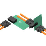
Wire-to-board connectors are used to connect a wire or group of discrete wires to a printed circuit board (PCB). These connectors serve as an efficient and cost-effective method for delivering power and signals to PCBs in automotive, industrial, lighting, and communication products. Commercial electronic equipment and household appliances often use wire-to-board connectors as well.

wire-to-board connectors shutterstock_2075457535
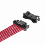
The needs of the application will dictate the style of connector chosen, as there are no “standard” wire-to-board connector designs. Depending on the manufacturer, some feature low-profile mating for tight spaces and various locking mechanisms such as friction lock, full lock, or quick disconnect. Others feature a locking bar or snap-fit type of connection to ensure the wire remains securely in its socket. While many connectors are surface mounted to the board, others have pins that go through the board and are soldered to the other side.

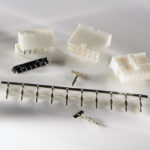
Wire-to-board connectors are specified by properties such as housing size, materials, number of contacts, stacking height (height of connector measured from the circuit board), length of contacts, and number of contact rows. They are also specified in terms of pin pitch, which is the distance measured between the centers of two conductors. Wire termination also differs based on the wire size and number of contacts. For example, connectors that handle significant power often have crimped-on contacts that are secured with some sort of tool. Other styles, such as mass termination connectors that hold 20 wires or more, can be designed for use in automated soldering systems.

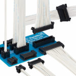
Another recent development is a new generation of ultra-compact connectors with profiles under 1.5 mm that are compatible with automated surface mount assembly in high-volume manufacturing. To ensure reliability, these tiny connectors often feature gold-plated contacts and strain relief capabilities. With so many sizes and styles available among today’s wire-to-board connectors, design engineers have more options than ever to select the right power and signal delivery system for their end products.

You may also like:

  • TE-connectivity-power-supply-connectors-D8000-Board
    High-current connectors increase power supply assembly efficiency and service life

  • Terminal block selection guide
  • TE Connectivity Val-U-Lok connectors
    New VAL-U-LOK connectors increase current ratings to 13 A
  • Hirose DF51 Series wire-to-board connectors
    Low-profile wire-to-board connector reduces system size
  • Molex MicroLockPlus wire-to-board connector 200_SNG_RA_5055700801 5055780801 - Mating
    Wire-to-board connector system ensures electrical, mechanical reliability

Filed Under: Basics, DW sync, EE sync, FAQ, Featured, Products, wire-to-board connector

Reader Interactions

Leave a Reply Cancel reply

You must be logged in to post a comment.

Primary Sidebar

Featured Contributions

From extreme to mainstream: how industrial connectors are evolving to meet today’s harsh demands

The case for vehicle 48 V power systems

SMP3 vs. SMPS: why two standards?

mmWaves bring interconnect challenges to 5G and 6G

Ensuring integrity in high-performance interconnects with connector backshells

More Featured Contributions

EE TECH TOOLBOX

“ee
Tech Toolbox: Internet of Things
Explore practical strategies for minimizing attack surfaces, managing memory efficiently, and securing firmware. Download now to ensure your IoT implementations remain secure, efficient, and future-ready.

EE LEARNING CENTER

EE Learning Center

RSS Current EDABoard.com discussions

  • 12VAC to 12VDC 5A on 250ft 12AWG
  • Lightbox circuit help
  • Engineer's own PCB layout software guide?
  • LVS Mismatch Error in Simple Layout
  • Does mobility carrier ratio changes with Wn? (0.18um) inverter design

RSS Current Electro-Tech-Online.com Discussions

  • How to repair this plug in connector where wires came loose
  • Lightbox circuit
  • Fuel Auto Shutoff
  • Kawai KDP 80 Electronic Piano Dead
  • Python help with keystroke entries

EE ENGINEERING TRAINING DAYS

engineering
“bills
“connector
EXPAND YOUR KNOWLEDGE AND STAY CONNECTED
Get the latest info on technologies, tools and strategies for EE professionals.

Footer

EE WORLD ONLINE NETWORK

  • 5G Technology World
  • EE World Online
  • Engineers Garage
  • Analog IC Tips
  • Battery Power Tips
  • DesignFast
  • EDA Board Forums
  • Electro Tech Online Forums
  • EV Engineering
  • Microcontroller Tips
  • Sensor Tips
  • Test and Measurement Tips

Connector Tips

  • Subscribe to our newsletter
  • Advertise with us
  • Contact us
  • About us

Copyright © 2025 · WTWH Media LLC and its licensors. All rights reserved.
The material on this site may not be reproduced, distributed, transmitted, cached or otherwise used, except with the prior written permission of WTWH Media.

Privacy Policy