The three basic types of shielding for electromagnetic interference (EMI) in cables include strands of braided copper and similar metals, spiral shields, and foil or tape shields. They can be used separately or in combination.
This FAQ begins with a review of the three types of shielding, then considers how they are used in combinations for applications like cables for variable frequency drives (VFDs) and Ethernet connectivity.
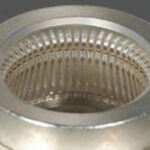
Metallic braided shielding can be made using bare, tinned, or silver-plated strands of copper, steel, or other metals. They are woven like fabric braids. Shielding effectiveness is proportional to the coverage of the braid over the wire. Most braided shields provide 75 to 85 percent coverage. Higher percentages are possible but can be prohibitively expensive. While it’s theoretically possible to get 100% coverage, that’s not a practical goal. Braided shields are often supplemented with a foil shield to increase shielding coverage for improved EMI performance (Figure 1). The braided shield has superior low-frequency performance, while the foil shielding provides higher-frequency shielding.

Due to their numerous performance benefits, braided shields are often found in military and industrial applications. In addition to EMI shielding braids can provide increased mechanical strength, flexibility, and physical protection for the cable.
Spiral shields are a variation of braided shields. They are formed with strands of shielding metal and are constructed by wrapping the shield material in one direction around the conductor with a second wrapping in the opposite direction. There is no interweaving of the shielding strands. They are lower cost compared with braided shielding and can achieve coverage of 95%, but they are found only in audio applications due to their frequency limitations.
Foils and tapes
The difference between foils and tapes is arbitrary and often depends on the manufacturer. Foils may be thinner metal layers compared to tapes, but that’s not always the case. Foils and tapes are often provided as a metal layer like aluminum or copper on a substrate called a tape made with mylar, polyester, or a similar material. They are sometimes referred to as foil tapes, adding to the confusion. These shields can be longitudinal or spiral wrapped around the cable. Longitudinal wrapping has lower inductance. While braided shielding is often used with heavy-duty cables with multiple wires and wire pairs, foils and tapes are usually used for individual twisted pairs or thin cables. The various types of shielding are often used in combination.
VFD cable shielding
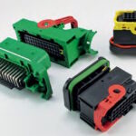
VFD cables are complex assemblies. They include wires for carrying the high-power pulse-width-modulated (PWM) signals for driving the motor, separate cables for braking, cables for sensing motor and environmental parameters, and so on. They use a variety of shielding materials including braids, foils, and tapes. They need high-voltage electrical isolation (from 600 to 15 kV) in addition to EMI protection. Due to the nature of the PWM drive, longer cables can be subjected to larger voltage spikes and require more robust insulation and shielding. There are many makers of VFD systems, and each one has a preferred cable structure (Figure 2).

Shielded category cables
Twisted pair cables used for Ethernet, also called Category cables, are often shielded from EMI. There is a wide range of environments where Ethernet is used, from relatively benign office or residential locations to challenging industrial settings. As a result, there’s an equally wide range of shielding structures associated with Category cables. The ISO/IEC 11801 standard defines standard acronyms to describe the various types of Category cable shielding structures.
The acronyms usually consist of two parts, before and after the ‘slash.’ The first code indicates the shielding over the entire cable and the second code indicates the shielding of individual twisted pairs. Examples include:
- F/UTP – Foiled cable/Unshielded twisted pairs These cables often include 4 pairs of unshielded twisted pairs and are used in 10GBaseT applications.
- S/UTP – Shielded cable/Unshielded twisted pairs.
- SFTP – Shielded and foiled twisted pairs for maximum EMI shielding.
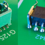
- SF/UTP – Shielded and foiled cable/Unshielded twisted pairs are common general-purpose Ethernet cables (Figure 3).
- S/FTP – Shielded cable/foiled twisted pairs minimize cross-talk between the twisted pairs.
- F/FTP – Foiled cable/Foiled twisted pairs are another common configuration used for 10GBaseT applications.
- U/FTP – Unshielded cable/Foiled twisted pairs is another configuration used for 10 GBaseT applications.
- U/UTP (UTP) – Unshielded cable/Unshielded twisted pairs for use in environments where EMI is not a concern.

Summary
EMI shielding for cables ensures reliable operation whether the EMI originates within the cable or in the external environment. While the various types of shielding can be used individually, they are often used in combination for improved performance. VFD cables vary based on the drive maker while Ethernet cables are standardized in ISO/IEC 11801.
References
Cable Shielding 101 – An Acronym Guide, ITM Components
Cable Shielding Types, Structured Cable Products
Popular cable shielding types, IEWC
Variable frequency drive cable solutions, Belden
Leave a Reply
You must be logged in to post a comment.