• Skip to primary navigation
  • Skip to main content
  • Skip to primary sidebar
  • Skip to footer
  • Advertise
  • Subscribe

Connector Tips

Connector Tips has connector and electrical connector news, product highlights and and editorial coverage.

  • Products
    • board-to-board
    • cable-to-board
    • power
    • RF
    • USB
    • wire-to-board
  • Electronics
    • bonding
    • copper
    • fiber
    • gold
    • optical
    • transistor sockets
  • Markets
    • Aerospace
    • Automation
    • Automotive
    • Electrification
    • Electrical & Instrumentation
    • Medical
    • Military
    • Off-Highway
    • Oil/Gas
    • Telecom/Data
  • Learn
    • Basics/FAQs
    • eBooks/Tech Tips
    • EE Training Days
    • EE Learning Center
    • Tech Toolboxes
    • Webinars & Digital Events
  • Resources
    • Design Guide Library
    • Digital Issues
    • Engineering Diversity & Inclusion
    • LEAP Awards
    • White Papers
    • DesignFast
  • Videos
    • EE Videos
    • Teardown Videos
  • Newsletter Subscription
  • Suppliers

RF edge connectors shrink in size, cover DC to 67 GHz

April 9, 2024 By Redding Traiger Leave a Comment

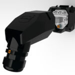
Samtec has released a new line of RF edge launch connectors with a narrow body design that is 33% smaller than traditional edge launch connectors. These connectors are commonly used in a lab setting for high-frequency test and measurement applications, high-speed digital component tests, and evaluation boards. Frequency capabilities are DC to 67 GHz (185-EL Series), DC to 50 GHz (240-EL Series), and DC to 40 GHz (292-EL Series). Interface types include 1.85 mm, 2.40 mm, and 2.92 mm.

As the name suggests, Samtec’s RF edge launch connectors are installed on the edge of the board. Doing so makes it easy to align the launch pin with the circuit trace, which also helps to ensure proper ground alignment for preventing RF leakage. Samtec’s RF edge launch connectors compression mount to the printed circuit board instead of requiring solder. Proper alignment and the removal of solder allow for increased signal integrity performance capabilities (versus soldered edge launch, or even vertical or angled launch connectors).

The solderless design of the 185-EL, 240-EL, and 292-EL Series connectors means they are reusable, also known as field replaceable; with up to 500 mating cycles, this makes them extremely cost-effective. Samtec’s RF edge launch connectors are easy to install and do not cause damage to a printed circuit board.

You may also like:


  • How does OPC UA PubSub data support connector digital twins?

  • How do connectors made with conductive plastics contribute to sustainability?

  • How does UCIe on chiplets enable optical interconnects in data…

  • What are the key design and selection considerations for MIL-SPEC…

  • What is the best copper alloy for connectors in renewable…

  • What plating options are available for high-power connectors?

Filed Under: connector components, Products Tagged With: samtec

Reader Interactions

Leave a Reply Cancel reply

You must be logged in to post a comment.

Primary Sidebar

Featured Contributions

From extreme to mainstream: how industrial connectors are evolving to meet today’s harsh demands

The case for vehicle 48 V power systems

SMP3 vs. SMPS: why two standards?

mmWaves bring interconnect challenges to 5G and 6G

Ensuring integrity in high-performance interconnects with connector backshells

More Featured Contributions

EE TECH TOOLBOX

“ee
Tech Toolbox: 5G Technology
This Tech Toolbox covers the basics of 5G technology plus a story about how engineers designed and built a prototype DSL router mostly from old cellphone parts. Download this first 5G/wired/wireless communications Tech Toolbox to learn more!

EE LEARNING CENTER

EE Learning Center

RSS Current EDABoard.com discussions

  • Phase Shift Full Bridge suffers spurious FET turn_ON
  • optimum spacing between feed and sub reflector
  • Equipment to see if household should buy battery/solar/inverter?
  • 'HERIC' pairs of IGBTs essential for Mains inverters
  • reverse polarity circuit protection between to power sources

RSS Current Electro-Tech-Online.com Discussions

  • Epson crystal oscillators
  • Simple LED Analog Clock Idea
  • Fun with AI and swordfish basic
  • Microinverters and storeage batteries?
  • PIC KIT 3 not able to program dsPIC

EE ENGINEERING TRAINING DAYS

engineering
“bills
“connector
EXPAND YOUR KNOWLEDGE AND STAY CONNECTED
Get the latest info on technologies, tools and strategies for EE professionals.

Footer

EE WORLD ONLINE NETWORK

  • 5G Technology World
  • EE World Online
  • Engineers Garage
  • Analog IC Tips
  • Battery Power Tips
  • DesignFast
  • EDA Board Forums
  • Electro Tech Online Forums
  • EV Engineering
  • Microcontroller Tips
  • Sensor Tips
  • Test and Measurement Tips

Connector Tips

  • Subscribe to our newsletter
  • Advertise with us
  • Contact us
  • About us

Copyright © 2025 · WTWH Media LLC and its licensors. All rights reserved.
The material on this site may not be reproduced, distributed, transmitted, cached or otherwise used, except with the prior written permission of WTWH Media.

Privacy Policy