Using one wire in two very different roles is widely done, requiring some simple circuity and basic components.
It makes a lot of sense to use an individual single copper cable and its connection between two points to do more than it initially intended, especially if that additional function is aligned with the primary function of the interconnections. For example, a low- or high-power line can carry data, a data line can carry power, and an audio line can carry RF. In some cases, having these wires to do “double duty” was part of their original design or intention; in others, it was an “add-on” devised after the original application or installation.
This article will look at three cases of such double duty and how they are implemented. These three cases share several common attributes: they are all designed to work exclusively with analog signals rather than digital ones; are relatively direct in concept and execution; require only a few passive components to function; do not have any sort of protocol, set-up function, or handshaking; do not require any state diagrams or firmware, and do not require any sort of link “authentication.”
The three double-duty techniques in this article are simple and require very few devices at each end. They are reliable and are still widely used even though they predate digital links. The three techniques we will look at are:
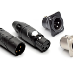
- Providing DC power to a microphone using the same shielded audio cable brings the microphone’s audio signal to the console/mixer amplifier (often called “phantom power”).
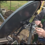
- Providing DC power to an antenna’s low-noise amplifier (LNA)/low-noise block (LNB) via the same coaxial cable, which brings the amplified RF signal to the receiver from the end.
- Using the headphone/earphone cable, which delivers audio power to the earbuds or headphones of a portable radio, MP3 player, or smartphone to also act as the FM-band antenna.
In some cases, it would be feasible to run two cables, but, in general, anytime you can leverage a cable and reduce the interface to a single cable, it’s easier from cost, physical installation, panel space, documentation, and reliability perspectives. Of course, that’s true as long as there are few or no negative consequences.
Data shows that problems with connectors and cables (loose, corroded, broken wire) are among the most common causes of hard or intermittent system problems. It’s not so much that a properly designed, fabricated, and installed cable can go bad (they do). Still, it increases the odds that one cable will not be working properly or will inadvertently be disconnected. There’s an engineering maxim that says, “a cable is a potential source of problems between two other potential sources of problems.”
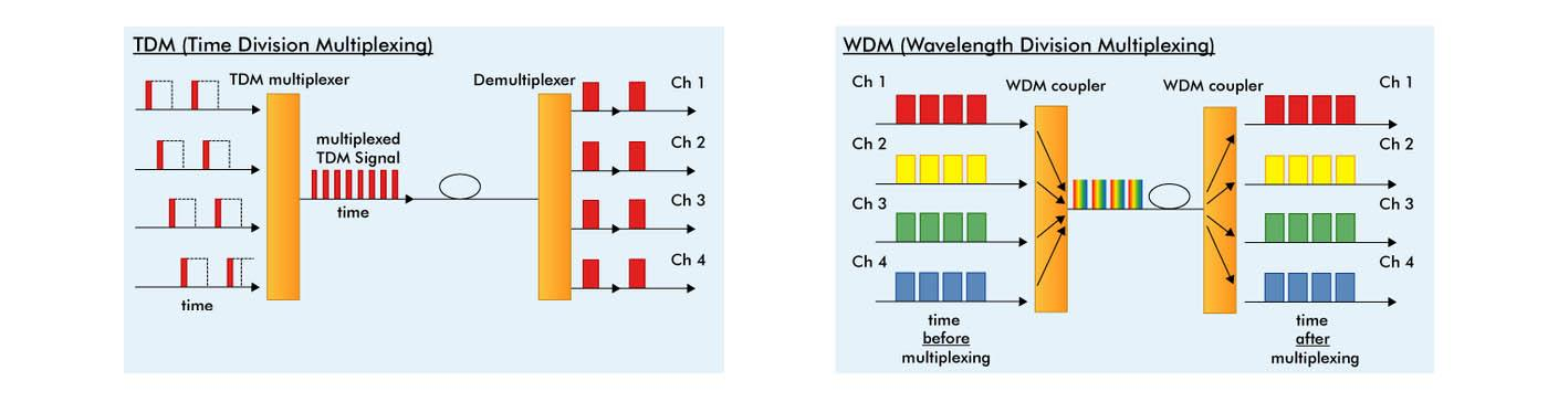
The challenge when sharing a single copper wire for two disparate functions is to superimpose them onto that wire without unacceptable interaction, interference, or crosstalk and then separate them at each end. But isn’t this the same as traditional multiplexing?
That depends on your perspective. If you view multiplexing as any superposition and sharing of two or more signals, even distinctly different signal and/or power, then yes, it is. Suppose you consider multiplexing to be the sharing of a single cable of nominally identical signal types (such as voiceband audio or RF channels) via time division multiplexing (TDM) or frequency (wavelength) division multiplexing (FDM). In that case, it is not (Figure 1).
These attributes contrast to many dual-use systems as defined by industry standards now in use, but which this article will not cover. Among these are:
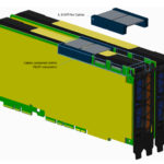
- Power over Ethernet (PoE) which can deliver almost 100 W to a load under its latest revision.
- USB Type C, which can deliver up to 3 A at 20 V (60 W) but can also carry higher current of 5 A at 20 V (100 W) under some configurations.
- Powerline networking as typified by the HomePlug Powerline Alliance and the IEEE 1901 standard, which uses the AC lines for data networking in a residential LAN, office building, or even wider area (each is a very different design scenario).
Why not discuss these three standards? There are several reasons:
- They are each extremely complicated and require sophisticated ICs at each end to verify their identity and validity, set up and initialize the connection, supervise the data flow, and coordinate handshaking and ongoing oversight.
- They each require lengthy discussion and explanation, which is well beyond the scope of this article.
- For PoE and powerline networking, they also require transformers for signal/data isolation and user safety.
- Even though they may appear to the user as “plug and play”, they are most definitely not, as each is defined by voluminous specifications. While this protocol and functional complexity are largely hidden from the user, it also means that a lot can malfunction anywhere from start-up to ongoing performance.
- Further, they are very difficult to troubleshoot, need software/firmware implementing state diagrams at each end to function, and are challenging to debug even for a knowledgeable professional with the specialized test equipment required.
The next parts of this article look at three distinct sharing schemes in wide use. They all use basic passive components and are elegant in their simplicity.
Related EE Word Content
- Triple-band GNSS low-profile helical antenna features small form factor
- Surface-mount antennas cover GPS high-precision, correction bands
- DLNA Approves HomePlug AV and HD-PLC Powerline Networking for Increased Digital Home Connectivity
- The complexity of wireless receiver testing
- Gadgets: Several Decisions To Be Made Before Selecting New Headphones
- Microphone Product Family Adds Calibrated System With Phantom-Powered Preamplifier
External References
- ProSoundWeb, “A Primer On Phantom Power For Condenser Microphones“
- SweetWater, “What is Phantom Power and why do I need it?
- Electrical Engineering,” Can anyone explain Phantom Power and, specifically, how it’s used in satellite television systems?“
- Elliott Sound Products, “48V Phantom Feed Supply for Microphones“
- Instructables, “Make a Mobile Antenna to Listen to FM Radio Without Headphones“
- Learning Electronics, “Antenna Input & Audio Lineout Adaptor For Portable Radios“
- Skyworks Solutions, AN383, “Si47xx Antenna Schematic, Layout, and Design Guidelines“
- NXP Semiconductor, AN11420, “NXP GPS LNA – GPS LNA voltage supply via a coax cable
coming from the GPS receiver“ - Maxim/Analog Devices, Application Note 6166, “MAX20328 Adds FM Radio Antenna Path to Smartphones with USB Type-C Interface”


Leave a Reply
You must be logged in to post a comment.