Fiber optic connector trends include a proliferation of new and smaller designs and, according to NTT, optical connector standardization activities are one of the most active areas at the International Electrotechnical Commission (IEC). As of February 2021, IEC SC 86B (Fibre optic interconnecting devices and passive components) published the second largest number of documents in IEC after TC 61 (Household appliance safety), with the second largest number of documents in work after TC 82 (Photovoltaic power generation).
This FAQ will review the shrinking of passive and active optical connectors, look at developments related to higher bandwidth optical interconnects and co-packaged optics, and along the way, review a small bit of the massive standardization activity in this area.
Broadly speaking, fiber optic connectors consist of two interrelated technologies, connector optical interfaces, and fiber optic connector interfaces, both of which are the focus of independent miniaturization efforts (Figure 1). Connector optical interfaces align and adhere to the fiber cores in a physical connection. Ferrules are used to align the fiber cores, and there are standards that specify the dimensions of the ferrules needed for the fiber cores to adhere. The ferrules are enclosed in connector housings that include springs to press the two sides together. Fiber optic connector interfaces standards specify the dimensions and spring force required in the connector housing,
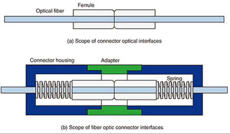
Until recently, the FC-style connector with a 2.5 mm ferrule was the most common fiber optic connector. It is being replaced by SC and LC connectors. The SC connectors also have a 2.5 mm ferrule, but replace the screw connection of the FC connector with a latch-style connection to simplify and speed deployments. The newer LC connector also uses a latch-style connection but has a 1.25mm ferrule to support increasing interconnect densities. The FC, SC, and LC connectors are all covered by IEC standards.
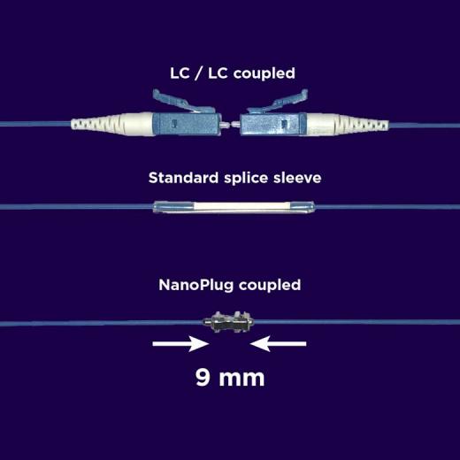
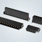
One of the latest developments is an optical connector that is one-tenth the size of an LC connector and does not require a splice tray for assembly while also providing good thermal performance (Figure 2). It’s available in a variety of connection styles and is designed for use in high-density 5G telephone, medical systems, and fiber optic sensing equipment. It’s currently in the IEC standardization process.
Active Optical Cables
Active Optical Cables (AOCs) are often used in data centers and high-performance computing networks such as InfiniBand. An AOC is a prefabricated assembly of two or more pluggable electronic modules with interconnecting fiber optic cable. By integrating the electronics and fiber, the overall solution size is decreased, and the performance is enhanced. Some implementations may have a single module on one end of the cable with multiple modules on the opposite end. For example, AOCs are available with a 100 Gb/s module on one end that feeds into four individual 25 Gb/s modules on the other end, enabling four servers to connect to a single switch port. Optical interfaces are called the physical medium dependent (PMD) layer by the IEEE and are generally defined by IEEE 802.3 Ethernet standards. However, for high-speed interconnects such as 100G Ethernet, standardization is an ongoing process.
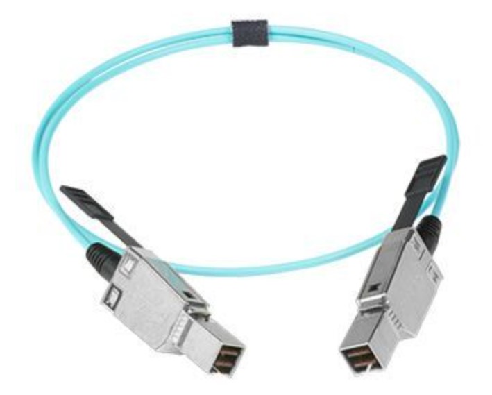
Mini AOCs are available that are compliant with SAS 2.1 (6Gb/s), and SAS 3.0 (12Gb/s) industry standards, as well as the SFF-8449 management interface for SAS, shielded cables, SFF-8636 common management interface, and SFF-8644 mini-multilane, shielded integrated high-density connector interface standards, all from the Storage Networking Industry Association (Figure 3). Mini AOCs are designed for use in high-density I/O applications in enterprise storage systems such as box-to-box, server-to-switch, server-to-storage, and so on. They support PCI Express Gen3 (8Gb/s) applications, can operate with up to 48Gb/s aggregate bandwidth, and are capable of transmitting up to 100 meters using multimode fibers.
Connecting supercomputers
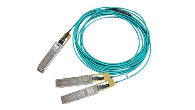
Vertical-cavity surface-emitting laser (VCSEL) technology is being used to build AOCs that deliver ultra-fast transmission capabilities, and that comply with class-4 quad small form-factor pluggable (QSFP+) power consumption requirement (Figure 4). While these AOCs are not necessarily smaller, they provide increased bandwidth in the same form factor, effectively shrinking the overall solution size. They have four HDR transceivers on each end with 100Gb/s HDR100 (2x 50G-PAM4) cross-connected at 100Gb/s. That enables linking four switches using only four switch ports with one AOC, instead of four separate cables and eight switch ports. These AOCs are designed for use in supercomputers that have stringent performance demands, exceeding Ethernet AOC industry standards, and are available to support short-, medium- and long-range scalability and a variety of interconnect topologies, with high signal integrity and reliability. They support quad data rates (QDR) and FDR10 (40G), FDR (56G), EDR (100G) up to 100m, and HDR (200G) and NDR (400G) up to 150m.
Co-packaged optics
To address next-generation bandwidth and power challenges in supercomputers and cloud data centers, there is a focus on replacing AOCs with higher density and higher speed Co-Packaged Optics (CPOs) (Figure 5). CPOs are an advanced heterogeneous integration of optics and silicon on a single packaged substrate. CPOs will merge fiber optics, digital signal processing (DSP), switch ASICs, and new packaging technologies. Today’s connector optical interfaces and fiber optic connector interfaces will be replaced with a single compact and high-performance integrated interconnect structure.
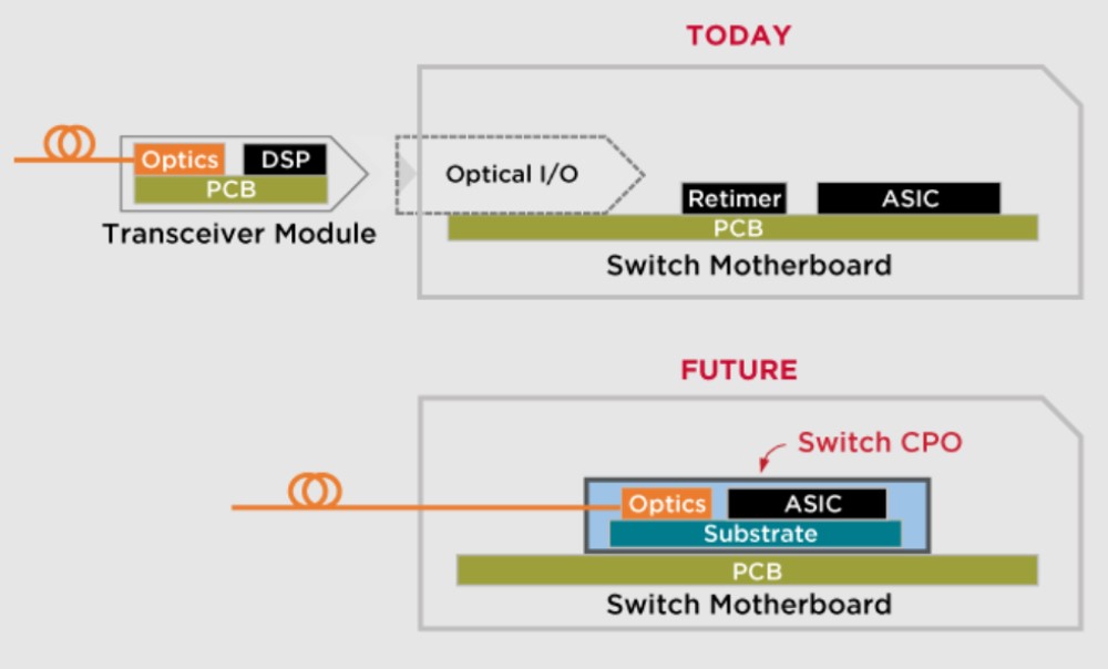
When implemented, CPOs are expected to have numerous benefits, including:
- 50% increase in rack density
- Higher bandwidth density
- Up to 500 Gbps/mm die edge
- Up to 64 single-mode fibers attached to a single die
- 30%, or more, reduction in power
- Interconnect power <1 pJ/bit
- System thermal management handling capability over 100 W/cm2
- Up to 40% lower per bit optics cost
- The use of integrated silicon photonics is expected to enable high-volume manufacturing
- Higher reliability and operational efficiency
The Co-Packaged Optics Joint Development Foundation (CPO JDF) has been formed to provide end-user guidance and recommendations to the industry for the development of open specifications to enable system integration of highly integrated optical components.
The CPO JDF has defined technical specifications for a 3.2 Tb/s CPO transceiver module that is expected to be a building block enabling a low power 51.2Tb/s switch, with 16 modules arranged around the edge of the switch ASIC. The CPO JDF has proposed two approaches to the development of a 3.2 Tb/s CPO transceiver, one based on 400GBASE-DR4 (with a total of 32 Tx/Rx fiber pairs), and one based on 400GBASE-FR4 (8 Tx/Rx fiber pairs).
The anticipated CPO transceiver module will include a digital signal processor, modulator driver and trans-impedance amplifier ICs, and integrated silicon photonics (SiPho). The 400GBASE-FR4 module specification includes an optical multiplexer and de-multiplexer sections and supports up to 3 km of duplex, single mode fiber. In addition, 400GBASE-FR4 modules will be available in two versions; one with an external laser source, and the second with laser diodes built into the transceiver using SiPho. The SiPho configuration includes backup lasers to ensure the required level of reliability.
CPOs may not be a panacea
The development of CPOs may also result in some disadvantages compared with today’s AOC approaches:
- The larger number of fibers connected to switches will increase the complexity of routing fibers from each CPO to the front panel and across the network, potentially reducing some of the benefits of the increased density of CPO interconnects.
- A switch with an integrated CPO could be difficult or even impossible to repair if the CPO fails. In the expected architecture, the CPO switch is directly soldered to the motherboard. If even a single fiber is damaged during the attachment process, the entire CPO will have to be replaced. In addition, if a CPO fails in the field, repair will be costly and could negate any anticipated cost benefits, increasing the operating costs of a data center and reducing its availability.
Summary
Optical connector standardization is one of the most active areas for the IEC. The miniaturization of fiber optic interconnects is being pursued for connector optical interfaces and fiber optic connector interfaces. One result has been the replacement of 2.5mm ferrules with 1.25 mm ferrules in standard optical connectors. Next-generation designs are in production, but not yet standardized, which reduces the size of these interconnects by a factor of 10. Active optical interconnects are also undergoing a miniaturization process that’s expected to lead to the development of CPO technology that will deliver a 50% increase in rack density, 30% less power consumption, and 40% lower effective cost/bit.
References
Co-Packaged Datacenter Optics: Opportunities and Challenges, Institution of Engineering and Technology
Co-Packaged Optics, Broadcom
Co-Packaged Optics Joint Development Foundation
Optical Metallic Connector that Fits in a Tiny Space, Sumitomo Electric
Recent Standardization Activities of Optical Connectors in IEC, NTT Technical Review
Storage Networking Industry Association, SNIA


Leave a Reply
You must be logged in to post a comment.