Amid a plethora of performance requirements for connectors used in heating ventilation and air conditioning (HVAC) systems and other harsh environments, five stand out as especially important — ingress protection against dust and moisture (IP rating), extreme temperature operation, balancing mating/unmating forces and contact resistance, retention force and locking mechanisms for robust operation, and safety.
IP ratings
The IP classification system is defined in IEC 60529. Connectors in HVAC and harsh environments often need a high IP rating. IP ratings consist of two digits. The first digit indicates the level of dust and object protection on a scale from 0 to 6. The second relates to the level of protection against liquids (Figure 1). For example, a connector with an IP68 rating is dust tight and can withstand powerful water jets directed at it.
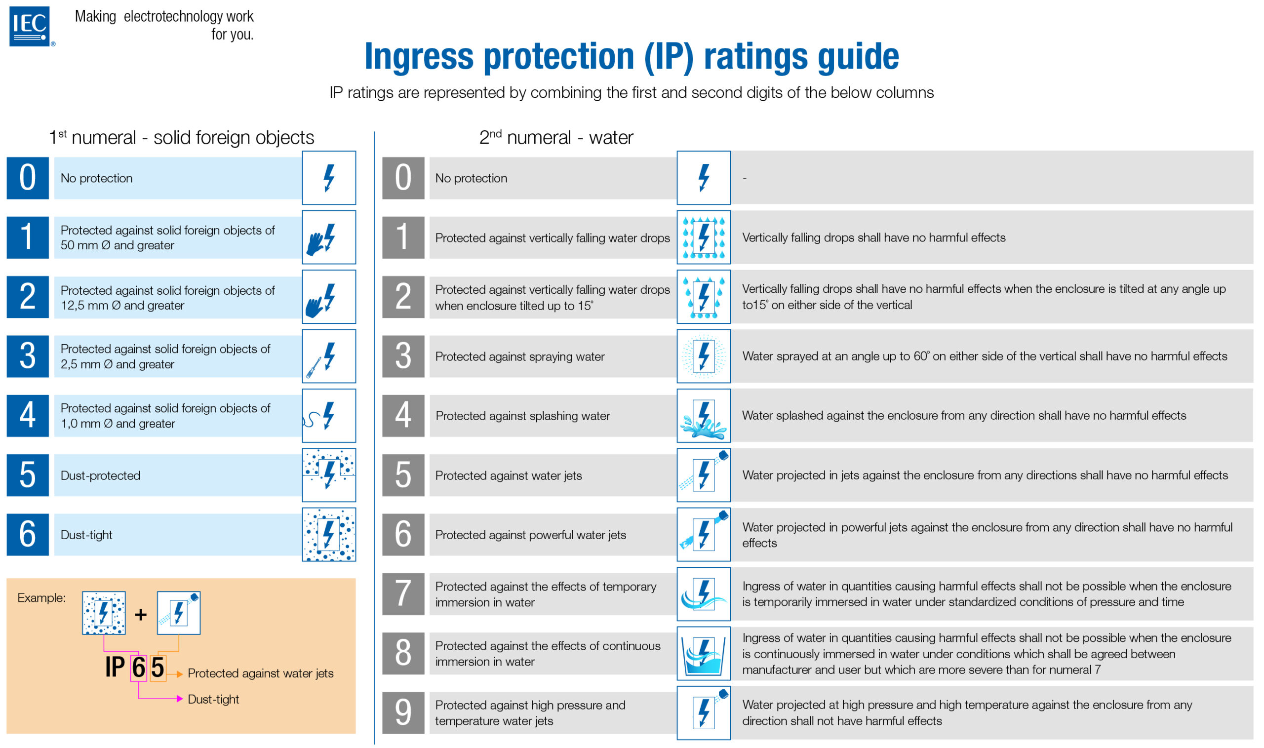
When specifying an IP rating, it’s necessary to consider how much exposure the connector will have to debris, tools, even fingers, and dust including very fine powdery particles, dirt, or sand, and whether the anticipated exposure is intermittent or continuous. Exposure to water is a major consideration for systems like HVAC that may be outdoors and exposed to the elements. IP ratings extend to systems that may be submerged.
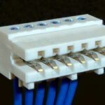
Some HVAC systems and equipment used in harsh environments may require sealed connectors with an IP68 rating. That can include wire-to-wire connectors and other interconnect styles (Figure 2). If connectors are not properly sealed, dust, water, and other materials can get inside the connector, and potentially inside the equipment, disrupt signals, corrode contacts, and cause physical damage to other system elements.

Not too hot or too cold
Connectors are thermally rugged components. But they have temperature limits. Many connectors are rated for operation up to 85 C°. In the case of HVAC and other harsh environments like industrial and automotive systems, that’s often not sufficient. An HVAC condenser system, for example, may be located on the sunny side of a building in a hot climate where temperatures may be excessive. In addition, the motor drive and other electronics in the compressor will dissipate heat, pushing the temperature higher. And the contacts in power connectors carrying high currents can experience some level of self-heating.
Connectors designed for use in HVAC and harsh environments are often rated for 105 C° or higher. It can also be important to make sure the connector can function reliably in unusually cold weather. That same compressor that experiences summer heat, may be exposed to sub-zero temperatures in the winter.
Mating force
Specifying the optimal mating force is complex. Too little mating force and the resistance between the contacts can be too high; too high a mating force can make it difficult to assemble the system without damage. The proper mating force together with an optimal contact geometry is necessary to support the specified contact resistance. Too high a resistance can decrease the transfer of power or signals or cause increased thermal dissipation. Two types of resistance affect connectors:
- Bulk resistance is caused by the material carrying the current and depends on the shape and material of the contact pins.
- Contact resistance is caused by the strength of the mechanical connection of the two connector sides and depends on the contact force between pins and sockets.
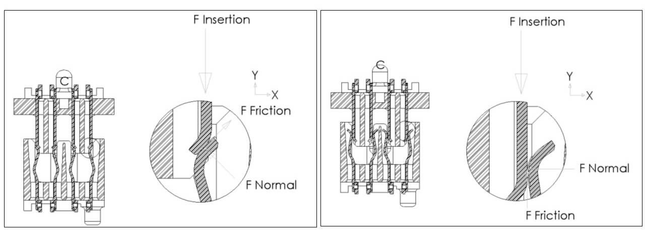
Contact resistance can vary depending on the normal force between the pin and socket. A high contact normal force results in the greatest surface area contact between the pin and socket and lower contact resistance. Designs with low normal forces can result in inefficient signal or power transfer. Connectors are designed to balance the highest practical normal force with a reasonable level of required mating force. Mating and unmating involve different combinations of forces, as a result, mating requires greater force than unmating. During mating, the contacts are first spread open as the pins and sockets come together. The force required during this phase is a combination of the insertion (spreading) force and friction (Figure 3). During unmating, the contacts naturally return to the original shape without requiring any force and the only force experienced is friction.
Retention force and locking mechanisms
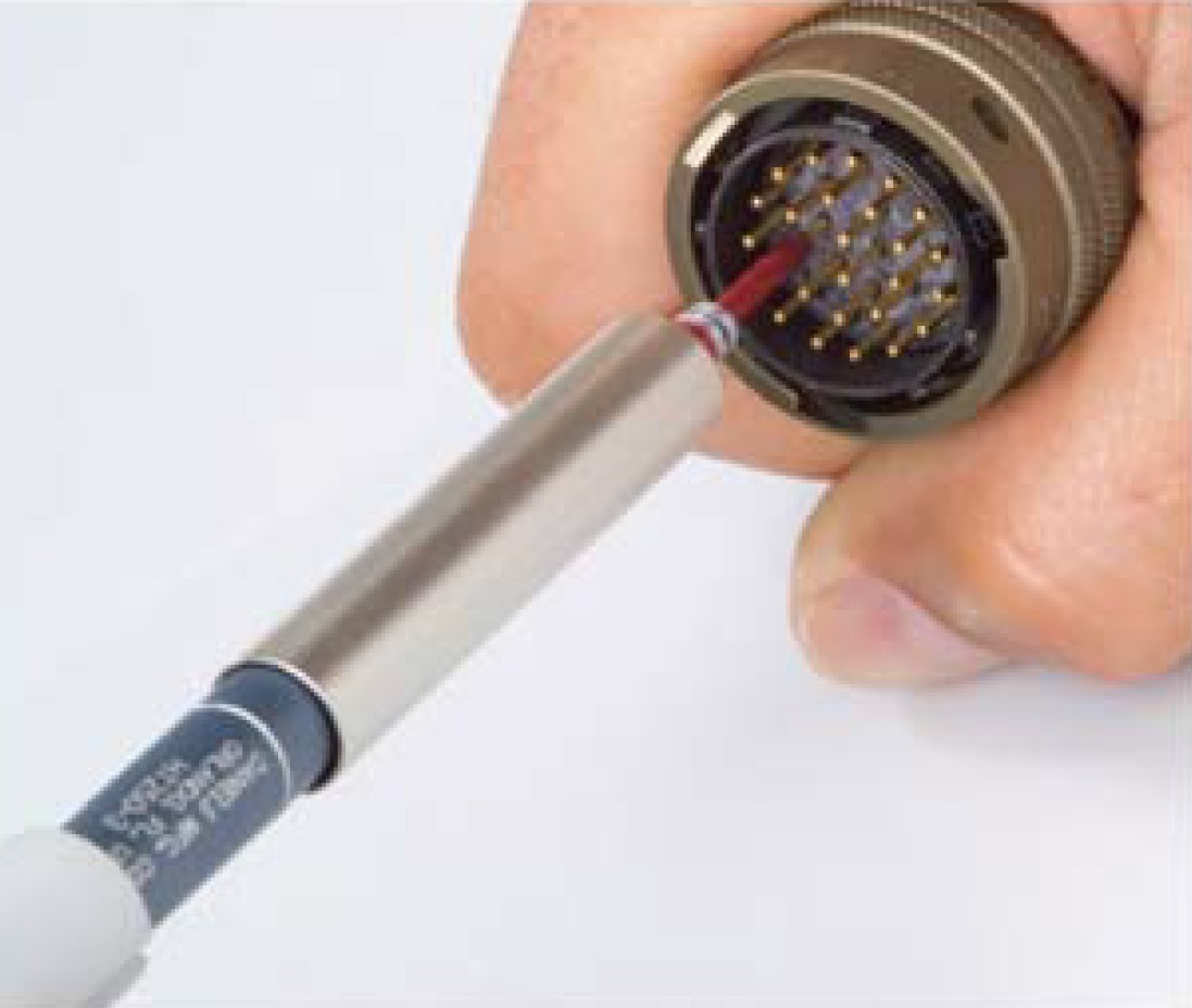
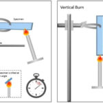
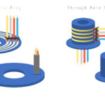
Retention force is not the same as unmating force. Unmating refers to disconnecting a connector. There are two definitions of retention force. One definition relates to how firmly the pins are held in the connector body. Adequate contact retention force is needed to absorb contact mating forces and resist forces resulting from normal use of the connector. Retention force is measured in Newtons, and the correct retention force reduces the potential for contact damage. EIA-364 MIL-DTL-38999 Method 4.6.32 defines the axial force necessary to displace a contact from the proper location when inserted into a connector. Manual and automated tools are available for measuring retention force (Figure 4).
The second definition of retention force refers to how firmly a plug is held by a receptacle. Pin and socket material and design impact retention force. For example, if a design calls for a high number of mating and unmating cycles, it can be desirable to minimize the spreading forces when mating the connector halves and achieve the desired retention force through friction.
Locking mechanisms are often employed to ensure robust connections without resorting to high levels of mating or unmating forces. A locking mechanism is a mechanical system that ensures high evels of retention force. It can be passive and automatically engaged when the connector is mated or may require the user to manually activate the lock. In both cases, the locking system helps maintain robust connections. It can also be used in environmentally sealed connectors to maximize the integrity of the seal.
Safety
There are several safety standards related to connectors. One of the basic standards is UL 1977 which covers single and multipole connectors used in data, signal, control, and power applications. UL 1977 requirements are guidelines and do not replace equipment or application-specific standards. It defines safety standards based on operating types. A connector without an assigned current rating is either a Type 0 or Type 1A or Type 5 depending upon its voltage rating. CSA C22.2 No. 182.3 is similar but with fewer device type categories. The basic device types defined in UL 1977 are:
- Type 0 rated less than 8.3 A and less than 30 V rms (42 V peak).
- Type 1A rated less than 8.3 A and from 30 V up to and including 600 V ac or dc, or both.
- Type 1B rated from 8.3 A up to and including 200 A, and less than 30 V rms (42 V peak).
- Type 2 rated from 8.3 A to less than 31 A and from 30 V up to and including 600 V ac or dc or both.
- Type 3 rated from 31 A up to and including 200 A and from 30 V up to and including 600 V ac or dc, or both.
- Type 3A rated from 31 A up to and including 200 A and from 601 V up to and including 1,000 V ac or dc, or both.
- Type 4 rated from greater than 200 A up to and including 1,000 A, and up to and including 600 V ac or dc.
- Type 4A rated greater than 200 A up to and including 1,000 A, and from 601 V up to and including 1,000 V ac or dc.
- Type 5 rated less than 31 A and from 601 V up to and including 6,000 V ac or dc, or both.
Other common safety standards for connectors include:
UL 2237 for multi-point interconnection power cable assemblies rated for up to 1,000 V.
UL 2238 for connectors intended for sensors and actuators in remote-control, signaling, and power-limited circuits rated 60 A or less and 600 V or less.
IEC 61984:2008 applies to connectors with rated voltages above 50 V and up to 1000 V AC or DC and rated currents up to 125 A per contact,
Summary
Connectors are important components determining robust system operation in a range of environmental circumstances and operating conditions. When specifying connectors, there are many factors to consider; among the most important are IP ratings, extreme temperature operation, balancing mating/unmating forces and contact resistance, retention force, and locking mechanisms for robust operation and safety.
References
Calculating Connector Mating Forces, Samtec.
Contact Retention Testing, CRiMP-TECH Australia.
Sealed Wire-to-Wire Connectors, Molex.
Specifying an IP Rating for Harsh Environment Electrical Connectors, PEI Genesis.
Leave a Reply
You must be logged in to post a comment.